In doing some research about output transformers for the EL84 I found this:
"Virtually all transformer manufacturers today think that "UL" operation is defined as 40%, so their entire line is often offered with that tap point, with little understanding as to how the tap %, the plate-to-plate load, and indeed the tube itself are all intertwined. The 40% point got it's start from the original UL experiments that were done on 6L6 class tubes, that respond most to the UL influence at 43.0% of the winding. But Hafler (and Keroes) quickly learned that the optimum tap % was not only tube specific, but also loading specific as well, such that the optimum tap % is hardly 40% for all tubes or conditions. Early on, much of the information was derived empirically, as was certainly the case for Hafler's original transformer, the A-430. This transformer was specifically designed for EL34 tubes, under conditions of maximum power output with minimum distortion. With a 4.3K primary, it employs taps at 33%. But raise the load to 6K plate to plate or greater, and the optimum point becomes 40% for these tubes. The difference is not insignificant. EL84 and 6V6 class tubes work best with a 25% tap. Using a 40% tap produces very compromised performance with these tubes. Overall power output suffers, and particularly so at the HF end of the scale. 6550s generally do like 40%. Real KT88 are good with anything from about 20% to 50%, because this tube was designed specifically with UL operation in mind, and the list goes on."
diytube.com :: View topic - ST-35 with Tango Output Transformers
Unfortunately the author speaks about power and not so much distortion.
Anyone care to comment on this?
Anyone care to comment on this?
UL: Urban Legend . . . beuark !

Compare drive requirement, output power and distortion.
My faith is to regulate the screen voltage.
Yves.
My faith is to regulate the screen voltage.
Yves,
If a tertiary screen grid winding on the O/P trafo is employed, both regulated g2 B+ and ultralinear, local, NFB are available. Vanderveen's writings cover the subject, to some degree.
------------------------------------------------------------------------------------------------------------------
All,
Bas makes a good point about the UL %. The highly revered "iron" Freed wound for the H/K Cit. 2 is tapped at approx. 20%.
Seven working amps in this house, all pentode mode. Three stereo amps, four guitar amps. There is nothing wrong with pentode mode IMO, in fact I like it the best  Some people like triode mode, or UL, and others must have varying degrees of global NFB, that's all fine, each to their own.
Some people like triode mode, or UL, and others must have varying degrees of global NFB, that's all fine, each to their own.I think pentode mode can offer the lowest distortion, provided you give the screens a good stiff supply..
You recon?
Intermodulation thd performance is lowest with 40% UL and highest with true tetrode. SOmewhere there is a KT88 chart which confirms this.
UL in an MI amp is an expensive non-luxury. For HiFi, that's different. With a decent amount of global nfb, should snuff UL 40% operation IM THD to well below 1% and harmonics F2,3 to a tenth below this. Triode operation has a slightly higher IM THD compared to UL 40%.
So UL with 40% tap offers the lowest IM THD so it claims the quality king. Debatable ??
richy
The way I see it, is that the purest way to linearise the output stage is actually global feedback, and anything that happens before than is convoluted, such as triode or UL mode. It's better to subtract the error at the beginning than try to do it with the screen grids (imo)
pushing the gain to the outer loop can be shown to be optimum for distortion reduction with non-interacting gain stages
many may not appreciate the extra linearizing consequence of added gain at the output stage - the signal level at all previous stages is reduced for the same output so the preceeding stages give lower distortion due to the lower signal/bias ratio
tube amps can be limited by output xfmr bandwidth so you may not be able to stablize the amp with higher global feedback
Triode mode and UL lose power capability in the output stage due to the feedback, and both suffer from plate or screen grid feedback not tracking grid1 non-linearity exactly. (triodes have the same non-linear issue as screen feedback since it is g1 gm that suffers the island effect, not g2 or plate) The best approach would appear to be global feedback around the OT up till the top of the audio band, then a frequency crossover to a primary side feedback (still to the input stage) to avoid the OT frequency limitations.
Several ways to implement that, but easiest is probably just using an inner loop that kicks in at 20 KHz or above (so greatly reducing the outer loop gain as a result). Putting that freq. crossover lower (in-band) would require careful design to prevent phase changes at the output within the freq. transition region, but the low performance/ low cost OTs around may require this.
Several ways to implement that, but easiest is probably just using an inner loop that kicks in at 20 KHz or above (so greatly reducing the outer loop gain as a result). Putting that freq. crossover lower (in-band) would require careful design to prevent phase changes at the output within the freq. transition region, but the low performance/ low cost OTs around may require this.
Here we go. Output transformer physics is the business end of tube amps.
For those who are looking for trouble, here it is in plenty.
Frequency distortion: Caused by too small prim L, too much leakage induct or resonant effects. These days not so much a problem.
Phase distortion: Caused by differences in phase when global nfb is used. Symptoms, HF parasitic oscillation caused by combination of phase differences from both high leakage inductance & high self capacitance leakage. Most amps I’ve seen have not been correctly optimised for this ! The trick is to design the closed loop response for equal stability at both frequency extremes. Too high global feedback generally makes this harder to achieve.
IM and THD: In o/p stage when primary L is too low causing overloading at low frequencies, this creates non linearity between I mag and B flux in the transformer core. Cure, for standard transformer sheet keep Bmax value low. This implies high Ae.
THD: Too high DC resistance of primary. Problem; power transfer load curve efficiency drops.
So generally the design should be aimed at,
High Prim L
Low leakage inductance and capacitance, this is the most serious conflict nub in modern day UL.
Peak Bmax in core allowed for.
Efficiency. Low losses in windings and core.
Matching of windings.
Sum up;, The resonant frequency caused by leakage L & C's determines the quality of the transformer.
There is alot more to all this; By coincidence, in a Williamson, the optimum closed loop Q or transient response damping occurs when o/p trans LF F2 THD occurs at 1.4% for a given F3 cutoff freq v.s core size and has a marked influence on sound quality. This depends on the type of transformer iron/alloy used. This implies the coupling cap values from the concertina and the o/p stage inputs should be properly calculated and not guessed at !
The Radiotron Handbook hasn't discovered the importance of the closed loop issue in detail, although the transformer math is physics clear. For coupling caps, see Morgan Jones, Valve amps 4th ed, p-83, p-190,p-585.
richy
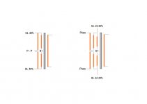
The "canonical" 43% is only the result of the winding scheme.
Yves.
hey, I just read a claim that the amount of UL percentage is related to the physical arrangement inside the tube
hey, I just read a claim that the amount of UL percentage is related to the physical arrangement inside the tube
It is called pseudo-science. You may create any pseudo-scientific theory relating almost anything.
yeah, I was a bit 'reluctant'
ultra-linear
also read original paper by Williamson, from 1953 or so
typical, can't find it now
he sure didn't like ultra linear very much
looked to me like he connected the UL tap to the catode
and cross referenced the PP plates
ahead of his time ?
and found this
http://www.angelfire.com/electronic/funwithtubes/6L6_Config.html
edit, well, this would be a Williamson schematic, yes ?
Attachments
dogma, pragma and kharma
I am now listening to P-P EL34.
The factory had used UL and fixed bias. I converted it to triode and cathode bias with Blumlien Garters. NFB network disabled.
The same OPT transformers now provide wider bandwidth and less distortion.
There is less power. Oh, the humiliation
I only use amplifiers to listen to Music. OK, and sound effects and test tones. I am not a purist.
I like to hear more of the Music. One way is to hear less of the amplifier.
Blumlien Garters automagically set the operating points of the opposing tubes to a point halfway between the normal for each, in this circuit. This minimizes the stress on each tube.
The currents through the two halves of the OPT primary are balanced at idle. This minimizes the magnetic distortion caused by unequal currents at idle. The OPT now does less when idle.
It was interesting to find that getting the amp to do silence better improved the sound. The sound continues to improve. The magnetic distortion done by unequal idle currents does not all vanish at once. Instant gratification is not the only kind.
Part of engineering is understanding how the system works and what can be done to improve the part I want, the sound. YMMV ;*)
Happy Ears!
Al
PS I can swap the output tubes to the opposite sides of the OPT and they still are balanced. Try that with fixed bias. For grins, I put an EL34 on one side and a 6550 on the other. Still balanced. Awesome.
- Status
- This old topic is closed. If you want to reopen this topic, contact a moderator using the "Report Post" button.
- Home
- Amplifiers
- Tubes / Valves
- UL for EL84. 22-24% is better than the dogma....40% is lowest distortion....