Hello SY:
I have been doing more playing around with my sound card, getting some really decent results (far as I can tell). My latest quandary is testing the differences between two types of differential circuits. I am getting some results that are very similar to the post here in your article:
http://www.diyaudio.com/forums/diya...tube-phono-preamp.html?garpg=13#content_start
And I thought you could shed some light on what I am getting. Background: the first page in the pdf is the partial schematic I am starting with (yes, the grids have a DC path to common). The other circuit I am comparing it to is identical, but removing the capacitor and placing a CCS under the cathodes, along with a 12V negative supply.
Second page is the test with the resistor tail. No problems so far. Third page is a shot of the noise floor. Again, I'm fine with that - being that I have a rat's nest for a circuit, with the heaters not elevated, I'm not overly concerned with the 60/120 etc hum products. Clean that up later.
Fourth page is where things get interesting. This is a test with the CCS in the tail. Harmonics are fine, but there is a lot of added noise as a result of the CCS above 3 kHz. Last page is the noise floor, with the same hash apparent.
Curiously enough, these last two FFT's look quite similar to what you posted in your article. And that circuit was also using CCS's in various locations. I tried different CCS's, single and cascode, larger negative supplies, etc - but all with the same basic result.
Is this behavior expected with the CCS? Thanks !
Attachments
I'm not sure I understand your circuit- did you draw it right? Double check and we'll see if there's anything odd that might make CCSes act funny.
In any event, the cascoded MOSFET CCS is ultra-quiet. Set up right, there should be no excess noise unless you have an oscillation.
In any event, the cascoded MOSFET CCS is ultra-quiet. Set up right, there should be no excess noise unless you have an oscillation.
circuit looks fine -- the 2x 5K resistors and the 50K pot make a shunting volume control. I think he just didn't draw either resistors from each grid to ground, or more likely an input transformer with the CT to ground.
An externally hosted image should be here but it was not working when we last tested it.
Sorry for the delay in getting back.
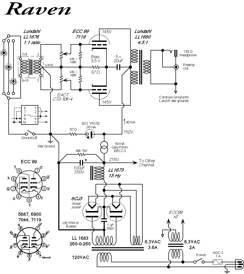
Yes, the 5K resistors and 50K pot are a shunt volume control. The actual signal circuit is a cross between the Raleigh audio and Raven circuit. For all intents, you can consider the first circuit under test to be a Raven fed with a phase splitting input transformer.
The second circuit under test removes the cap from B+ to cathode, and replaces the resistor with a CCS. SY, I have used negative supplies for the CCS. -12V or -24V, no difference.
I thought it was oscillation as well, but it looks identical to what you posted in the article....?
Last edited:
I thought it was oscillation as well, but it looks identical to what you posted in the article....?
Actually, I'm not sure of the cause of the noise in my spectra, but since it was ridiculously below audibility, I didn't chase it any further. You do have me curious... Nonetheless, the topologies are entirely different than yours so I wouldn't ascribe it to the CCS as a first guess. Did you look at the noise at the cathode junction? And what happens if you put the 15u cap back in while using the CCS?
This should address most of the questions. I did a more thorough job documenting exactly how the circuits are arranged, and modified the tube used. Really shouldn't make a difference, but at least there is no question about what was done.
That capacitor definitely cleaned things up, but I am surprised it would be needed. I would guess most fully differential circuits are not this noisy.
I have three different CCS's, all using the DN2540. One is single, two are cascodes. Identical results for each. 1K gate stoppers right at the pins.
PDF optimizer does not work too well; trying to get everything into a 200k file is challenging.
Attachments
Ah, interesting questions.
I followed prevalent 'best practices' when dealing with a two-pinned grid, which was a individual grid stopper tied together at the other end, where the input signal terminates. I did check individually and together, with identical results. The 12B4 isn't exactly high transconductance.
Also checked with and without meters, with no appreciable difference. That was a good catch- never considered it.
I did manage to clean up the 60Hz hum significantly by swapping in some other tubes. That was nice to see. However, I still have the bullywooger behavior between 3 and 10kHz.
- Status
- This old topic is closed. If you want to reopen this topic, contact a moderator using the "Report Post" button.
- Home
- Amplifiers
- Tubes / Valves
- Ping SY: His Master's Noise

