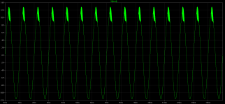
Here is my .asc It's exactly the same as yours. The problem is in my Ltspice models of 6N1P (not in only one). Look at the pic - somethings go wrong. With yours model I have the same THD results as you. I'm a little confused 
Edit: What's the best - I used your tubelibrary.txt in my other .asc files with other tubes and I have a lower THD results. So where's the point - which models give the most realistic results?
Edit: What's the best - I used your tubelibrary.txt in my other .asc files with other tubes and I have a lower THD results. So where's the point - which models give the most realistic results?
Attachments
Last edited:

I have noticed the big difference between 6N1P and 6N1P-EV data.
The "original" (old) 6N1P data shows 14mA anode current at 100 V Ua and 0 V Ug.
The new, Svetlana 6N1P data show 8 mA at these same conditions.
This is the same as the values of 6N1P-EV.
Eugene V. Karpov's model seems identical to 6N1P-EV and Svetlanas 6N1P data.
I have only used 6N1P-EV, but I doubt that 6N1P is that much different.
Can anyone confirm that the old 6N1P data is correct ?
Last edited:
With the different model suffixes and the large tolerance in tube manufacturing, all results from SPICE simulations have to be taken with a grain of salt, but at least, we can explain/investigate the difference in the THD/performance figures due to the use of different SPICE models.
I found some test plots of 6N1P and 6N1P-EV that I have done at 2011.
These are quite identical and close to Karpov's 6N1P model, 6N1P-EV data and Svetlana's 6N1P data.
These are quite identical and close to Karpov's 6N1P model, 6N1P-EV data and Svetlana's 6N1P data.
Attachments
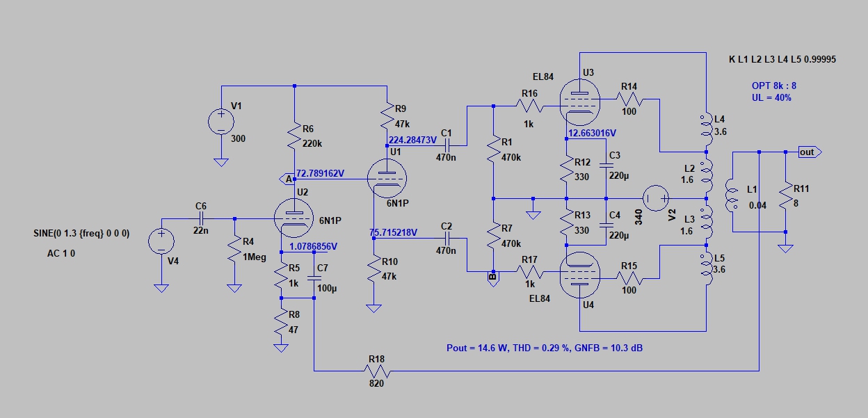
I made a modified (optimized) version and run some simulations with it.
It is better to have separate cathode resistors for output tubes.
A shared cathode resistor magnify the anode current unbalance, separate resistors reduce it.
This lessens the need to have well matched output tubes.
The gain of 6N1P is a bit low for this application. Therefore I modified the voltage amplifying stage to give maximum.
Also some 10 dB of GNFB is added. Now the performance is quite satisfactory. Sensitivity for full power is 0.92 Vrms.
I had the parts so I tried this in real life. Measurement results show:
-13.4W @ 1kHz before clipping
-Full power THD+N @1kHz 2.83% (mostly 3rd order harmonics)
-5W @ 1% THD+N (1kHz)
One strange thing though, if I connect the feedback to the 8ohm "positive" side of the OPT secondary winding, the channel goes crazy, but if I connect it to the common side, it works fine.
-13.4W @ 1kHz before clipping
-Full power THD+N @1kHz 2.83% (mostly 3rd order harmonics)
-5W @ 1% THD+N (1kHz)
2.83 % THD at 13.4 W AND with 10 dB NBF is poor result.
How much is THD without GNFB ?
... the channel goes crazy.
That is fully normal.
If you reverse the polarity of the output transformer (primary or secondary), negative feedback is changed to positive feedback.
That's why the amplifier goes grazy, i.e. begins to oscillate.
I must have something connected wrong here. I cleaned up the wiring a bit and connected the 820ohm resistor and I got about 2.5% THD. Then I disconnected the feedback and the THD was about 2.7%. Then I tried a variety of different value resistors and the lower the value, the less THD I got. Finally I just connected the transformer secondary directly to the junction of the 1k and 47ohm resistors and I got 1.39% THD.
Last edited:
When you "close" the GNFB-loop by connecting the 820 ohms resistor, the output level
(and sensitivity too...) should drop some 10 dB.
How much the output voltage drop (in dB) when you connect/disconnect the secondary from the junction of the 1k and 47ohm resistors ?
Do you have one end of the secondary connected to GND ?
(and sensitivity too...) should drop some 10 dB.
How much the output voltage drop (in dB) when you connect/disconnect the secondary from the junction of the 1k and 47ohm resistors ?
Do you have one end of the secondary connected to GND ?
I'll have to double check the wiring and resistor values tomorrow and do some more measurements. Yes, the OPT secondary is grounded at the same end (common) where the feedback goes back to the 6N1P. If I ground the other end of the secondary winding, again the channel goes nuts.
OK so I checked my wiring which was correct except that I had the wrong end of the OPT secondary grounded. If I grounded the correct end, the other channel went nuts, so I just disconnected the channel completely. Makes sense now that I think of it. Probably not the best idea to have two different channels fed by the same power supply... Now I have one channel running at close enough voltages.
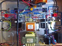
Anyway, the wiring still isn't the cleanest ever but here's what I measured:
-10dB GNFB
-13.7W @ 1kHz
-1kHz THD+N 0.885%
Without feedback the THD @ 1kHz is 2%
Anyway, the wiring still isn't the cleanest ever but here's what I measured:
-10dB GNFB
-13.7W @ 1kHz
-1kHz THD+N 0.885%
Without feedback the THD @ 1kHz is 2%
Yes, but two different ones doesn't seem to be. The OPT of the other channel started buzzing like a bee on cocaine once I grounded the secondary of the other channel. Now I have both channels assembled per artosalo's schematic and everything is working fine.
With GNFB both channels give me very similar results and without the feedback loop one channel gives me 1.6% THD and the other gives me 1.2%. I haven't actually listened to the amp yet, but it looks like we have a winner.
With GNFB both channels give me very similar results and without the feedback loop one channel gives me 1.6% THD and the other gives me 1.2%. I haven't actually listened to the amp yet, but it looks like we have a winner.
I know I'm starting to repeat myself, but I got the wiring pretty much finished except that I have to buy a couple of switches for the feedback loop and wire them in. Measurement results improved a little as well. The ones I mentioned above were actually false readings. I had the input signal turned down way below clipping when I took those measurements.
in UL without feedback I get:
-13.7W full power
-THD+N 1.85%
-8.8W power 1% THD @ 1kHz
- -1.6dB @ 20Hz / +0.3dB @ 20kHz
with 10dB GNFB I get 0.7% THD+N @ 1kHz at full power
In triode mode without feedback I get:
-6W full power
-THD+N 1.46%
-4.4W power @ 1% THD
- -0.3dB @ 20Hz / -0.3dB @ 20kHz
with 10dB GFNB I get 0.68% THD+N at full power
Both channels behave very similarly.
Attachments
According to LT Spice and this circuit:
- In triode mode, the open loop gain is 28.0 dB
- With R18 = 820, gain is 20.4 dB---> GNFB = 7.6 dB
- With R18 = 560, gain is 18.4 dB---> GNFB = 9.6 dB
- In UL-mode, the open loop gain is 32.4 dB
- With R18 = 820, gain is 22.0 dB---> GNFB = 10.4 dB
- In triode mode, the open loop gain is 28.0 dB
- With R18 = 820, gain is 20.4 dB---> GNFB = 7.6 dB
- With R18 = 560, gain is 18.4 dB---> GNFB = 9.6 dB
- In UL-mode, the open loop gain is 32.4 dB
- With R18 = 820, gain is 22.0 dB---> GNFB = 10.4 dB
- Home
- Amplifiers
- Tubes / Valves
- Unexpectedly good EL84 amp