I recently threw together my first tube regulator inside my main amp, with 6e5p's. It worked out so well I decided to make another for my RIAA amp, this time with higher voltages and more current capability.
Attached is the schematic. The 470V reading is with a load of about 75mA. The output stays at 360V with 75mA or without any load. PSUDII simulation says that the ripple at the last cap (the 470V spot) is around 25mV. I have no means to measure the ripple at output, but with listening tests done with headphones and volume at comfortable listening levels + 20%, there really is no ripple. I mean I couldn't tell if the RIAA amp was on or not! With volume maxed, there is still hum, but that volume with any music would break my headphones.
The regulator really improved the RIAA amps sound much more than I expected. I suppose not having big electrolytics in the audio path anymore really makes a difference.
I am by no means acustomed to designing small signal pentode circuits - my only prior experience with them is in the instrument world, and there if you don't have smoke coming out of your components and the sound is good you're pretty much ok. So I would like any input on the error amp design.
Also, how much current would you say those parallel 6V6GT's are capable of putting thru? I'm thinking about a project that would need about 120mA, and I'm wondering will these pass tubes cut it, or if I should buy something else.
Thanks.
Attachments
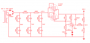
A single 6V6GT has a plate dissipation of 14 watts. With a voltage differential of 110 volts and a current of 120mA, you're dissipating 13.2 watts. So two 6V6s is good. Only one is at the limit with not enough reserve.Also, how much current would you say those parallel 6V6GT's are capable of putting thru? I'm thinking about a project that would need about 120mA, and I'm wondering will these pass tubes cut it, or if I should buy something else.
Edit: Of course you could use a single 6L6GC instead. And then there's the old trick of bridging the pass tube with a suitable 10W WW resistor to share the current (although ripple increases) while the tube maintains the regulation. However, for class A circuits that consume a fixed amount of current, regulation becomes less important.
Last edited:
When you have two pass tubes conected parallel, it would be good idea to have small (up to 50 ohms) series resistors at the anodes of both 6V6 to compensate the possible difference between the tube characteristics. Otherwise one tube can pass essentially bigger current than the other and thus get overloaded.
I think the filtering network prior to pass tubes is a bit overdesigned since the regulator itself will attenuate most of the hum.
PSUDII simulation says that the ripple at the last cap (the 470V spot) is around 25mV.
I think the filtering network prior to pass tubes is a bit overdesigned since the regulator itself will attenuate most of the hum.
artosalo:
That's a good idea, I should put those plate stoppers in!
I don't know about overdesign. Before this regulated supply I had a CLCLC with (PSUDII simulated) 6.9µV of ripple - it was very well audible at normal listening levels, though acceptable. The RIAA amp has quite a bit of gain with two mu follower type 6C45P stages.
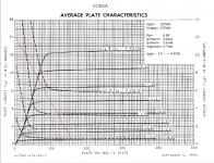
The design is quite similar to this screen voltage regulator I did for another project (attached). As for designing with pents, it's simply a matter of loadline selection (attached). Here, you don't need to worry about straying out of the saturation region since Vgk will be quite small anyway. Once you get this regulator adjusted, it'll stay on track for a good long while.
As for caveats, screen stoppers for all screen grids, grid stoppers, and bypass the screen of the pentode error amp.
If paralleling pass tubes, it's always best to include ~100R resistors at each cathode to ensure current balance. For higher current duty, you could parallel 6V6s, or make a pseudotriode from a TV HD power amp type, or use the 6AS7 as RCA intended: a series pass regulator. Two paralleled sections of a 6AS7 will easily handle 120mA.
Attachments
artosalo:
That's a good idea, I should put those plate stoppers in!
I don't know about overdesign. Before this regulated supply I had a CLCLC with (PSUDII simulated) 6.9µV of ripple - it was very well audible at normal listening levels, though acceptable. The RIAA amp has quite a bit of gain with two mu follower type 6C45P stages.
I suspect source of this hum in your case are either heater wiring or layout which need to be redesigned.
After reviewing my memos I agree with Miles. Cathode resistors are preferred over anode resistors. Here is Tung-Sol 6AS7G data and there are a lot of usefull application information concerning regulator tubes.
http://www.mif.pg.gda.pl/homepages/frank/sheets/127/6/6AS7G.pdf
In this case the source of hum is somewhere else.
http://www.mif.pg.gda.pl/homepages/frank/sheets/127/6/6AS7G.pdf
Before this regulated supply I had a CLCLC with (PSUDII simulated) 6.9µV of ripple - it was very well audible at normal listening levels, though acceptable.
In this case the source of hum is somewhere else.
LinuksGuru & artosalo:
You must be thinking of speaker systems. I listen with headphones, and in the headphone world 1mV of ripple is the absolute upper limit for ripple - it is already very very annoying. Generally if you want decent performance with headphones, you should have something in the 500µV range, and for good performance no more than 100µV of ripple.
With speakers, I couldn't notice any hum at all with several mV's of ripple. It's a different ball game.
As for the RIAA amps hum before and after the new PSU:
1) The signal chassis is untouched; all the same (DC) heater wiring and layout, yet with the new regulator - no hum.
2) The RIAA amp has a lot of gain - two stages with both a bit under 40 times voltage gain. For the sake of argument, let's call it 30.
If we take the previous ripple 0.0069mV, and put it thru the first gain stage, we have 0.207mV of ripple. Then thru the second, and we have 6.21mV of ripple riding on the signal going into the main amp! This would be completely unbearable with headphones, yet pretty good on speakers.
In reality of course the ripple is also attenuated between the two stages, and the mu follower topology isolates a lot of the PSU ripple from the signal parts. Still, with the previous unregulated supply, there was a noticeable, yet manageable amount of hum.
With this regulator, there is no more hum at all with any reasonable listening levels (with headphones).
- Status
- This old topic is closed. If you want to reopen this topic, contact a moderator using the "Report Post" button.
- Home
- Amplifiers
- Tubes / Valves
- Tube regulator