So, I'm new to the forums and I'm starting on my first tube project which involves converting an old Grommes/Precision Electronics S35 tube PA into a guitar amp. It's current running two 6eu7's for the preamp, a 6c4 for phase inversion, and 7868's in PP for the output stage.
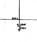
Before modifying anything I was looking over the schematic, it appears that one of the power filtering capacitors was spec'ed out to 250VDC when its rail is designed to operate at 325VDC. Could this possibly be correct??
full schematic (if interested):http://ampslab.com/SCHEMATICS/GrommesS35.gif
Before modifying anything I was looking over the schematic, it appears that one of the power filtering capacitors was spec'ed out to 250VDC when its rail is designed to operate at 325VDC. Could this possibly be correct??
full schematic (if interested):http://ampslab.com/SCHEMATICS/GrommesS35.gif
Attachments
You can do 2 things, measure the voltage to see if it exceeds 250v or just replace that capacitor with a 10uf/450v capacitor.
At first I thought maybe the 22K resistor dropped the voltage a bit but with 325 volts listed on the schematic, its possible the schematic is wrong.
Sal
At first I thought maybe the 22K resistor dropped the voltage a bit but with 325 volts listed on the schematic, its possible the schematic is wrong.
Sal

Get that 250Vcapacitor out of there! That's an accident just waiting to happen. According to that schemo, it's connected to a line that could go as high as 460V, with just resistor series drops to limit the voltage. It should be a 450V capacitor at least.
I don't know if that was an accident, or was done deliberately to keep the knowledgeable from building one of their own, but it's definitely wrong.
I don't know if that was an accident, or was done deliberately to keep the knowledgeable from building one of their own, but it's definitely wrong.
- Status
- This old topic is closed. If you want to reopen this topic, contact a moderator using the "Report Post" button.
- Home
- Amplifiers
- Tubes / Valves
- Capacitor Sanity Check