Ditch the EF80's and use ECC81 or ECC83 instead, otherwise it'll be OK.
Henry
Any reasoning for that?
Or drop one EF80 and tie the remaining in true penthode
Yves.
Ummmm, it's supposed to be a constant current draw stage. Note how the load resistors match.
EF80 looks acceptable when triode-strapped. Tom Schlangen has the curves. Going for ECC81 would probably degrade, ECC83 shouldn´t be mentioned as driver .
Would that make things sound better?
If going EF80 pentode you should also go Schade.
constant current draw stage
Would that make things sound better?
If going EF80 pentode you should also go Schade.
. . .
If going EF80 pentode you should also go Schade.
Do you suggest using the KT77 in Shaded penthode mode ?
I would agree with that !
EF80 looks acceptable when triode-strapped. Tom Schlangen has the curves. Going for ECC81 would probably degrade, ECC83 shouldn´t be mentioned as driver .
Would that make things sound better?
If going EF80 pentode you should also go Schade.
It will. CCDA: constant-current-draw amplifier
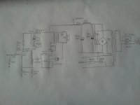
I thought about Schade, but the extra regulator required is too complex for my feeble mind. And the power is enough as is. Actually, I was expecting a discussion about operating points etc. I forgot to draw the primary impedance of the O/P transformer, it's 4.5KΩ
So just because of Broskie did it, it will sound good
 ?
? Add a DC-connected CF if you want to go A2.
Try redoing his math while you assume the internal resistance of your 'perfect' triodes has changed just 10% due to aging or normal parameter spread, like for instance Ri = 11K. Now your currents are suddenly off more than 10%. This will be worse still if the tubes were not perfectly matched to begin with, or if they drift apart as time passes (which they probably will).
Good tube schematics will consider tube imbalances and aging as a natural part of the design specifications. A design needs to be able to adjust gracefully for tube aging, whether manually or automatically.
Anything else is just a complete waste of perfectly good tubes IMHO, when people try to achieve perfect balance from their 'bad' tubes over time. TANSTAAFL.
The schematic may work perfectly for your application, but current balance is not something I'd consider a goal or a design parameter for the configuration.
Many of the modern 'perfect' tube designs seems to suffer from this lack of foresight, unfortunately.
- Frank.
So just because of Broskie did it, it will sound good
Add a DC-connected CF if you want to go A2.
No interest in A2, seems a waste of effort, if you look at the curves. I am not an engineer, i just try to make something based off what i have read. I'm like people telling me to go Shade, because it seems to be trendy in here.
Even if it does not balance perfectly (what's perfect, anyway), is it not a good idea, to have a grounded cathode, then a cathode follower to drive the final?
It is, IMO, yet that is not the point Broskie makes.Even if it does not balance perfectly (what's perfect, anyway), is it not a good idea, to have a grounded cathode, then a cathode follower to drive the final?
In the article you linked, he states that current balance in this configuration would lessen the requirements for expensive supply rail decoupling. Which is bad design, IMHO.
Nor does his math consider that the gain stage works with changing grid voltages, non-linearity and all, while the CF is running at nearly constant grid bias. The effects from this is likely to be lower than those due to tube imbalances, but it won't be zero, not even from perfectly matched tubes.
If one did not use sufficient decoupling of the driver supply rail, then you'd *definitely* hear a quick change in subjective performance as the tubes age (assuming they are somehow/magically perfectly matched to begin with).
And if we cannot assume perfect balance even with perfectly matched tubes, then this whole article is null and void.

I did state the configuration may work well for you, thinking of it as you suggest like a gain stage followed by a CF. This would be true if you ignore the current balancing argument and just use sufficient supply rail decoupling.
- Frank.
My point here is not that i am going to skimp on decoupling. CCDA is a nice added bonus, to an already sound topology. Enough of bashing, ok? Let's call it "not trendy" and leave it at that?
Anything about operating points? Anyone? Amount of feedback from the cathode of the output tube?
Anything about operating points? Anyone? Amount of feedback from the cathode of the output tube?
Last edited:
IMHO, if you are going to use an EF80, Schade seems the most logical choice, running both the input and output in pentode. I can't say i see any need for an additional regulator as both input and output run pentode, their near-current source behavior makes the output of the driver referenced to the supply rail, while it's input remains referenced to ground as usual. There are two things you can do to prevent the ripple in th einput stage get into the output stage:
1) You can filter/regulate the plate supply for the driver pentode. In reality, a simple RC filter will do just fine, provided you also match it's time constant with the cathode resistor and bypass of the output BPT.
2) You could bypass the cathode of the output BPT to it's plate supply rather than ground. This will effectively move the reference of the input signal to the BPT to the plate supply, which can then be made the plate supply for the input pentode. Because both the pentode and the BPT are close to current sources, their plates 'move' with the plate supply ripple, so getting the cathode of the BPT to do the same cancels out the ripple injected into the plate of the input pentode. This techique saves you one large capacitor, that would be used as a filter for the input stage plate supply, at the expense of rep[lacing the cathode bypass of the output BPT with a high voltage capacitor.
BTW CCDA might not be the best choice here, consider what happes when the amp goes into clipping (grid of BPT driven positive)...
Last edited:
IMHO, if you are going to use an EF80, Schade seems the most logical choice, running both the input and output in pentode. I can't say i see any need for an additional regulator as both input and output run pentode, their near-current source behavior makes the output of the driver referenced to the supply rail, while it's input remains referenced to ground as usual. There are two things you can do to prevent the ripple in th einput stage get into the output stage:
1) You can filter/regulate the plate supply for the driver pentode. In reality, a simple RC filter will do just fine, provided you also match it's time constant with the cathode resistor and bypass of the output BPT.
2) You could bypass the cathode of the output BPT to it's plate supply rather than ground. This will effectively move the reference of the input signal to the BPT to the plate supply, which can then be made the plate supply for the input pentode. Because both the pentode and the BPT are close to current sources, their plates 'move' with the plate supply ripple, so getting the cathode of the BPT to do the same cancels out the ripple injected into the plate of the input pentode. This techique saves you one large capacitor, that would be used as a filter for the input stage plate supply, at the expense of rep[lacing the cathode bypass of the output BPT with a high voltage capacitor.
BTW CCDA might not be the best choice here, consider what happes when the amp goes into clipping (grid of BPT driven positive)...
starting too look interesting... If only i understood what the BPT is. Care to elaborate?
BPT = beam power tube, i.e. KT77
Not quite a pentode, it's a kinkless tetrode with a virtual G3. I should mention that the beam plates in a BPT do NOT have the same function as G3 in a pentode, they just dierct the flow of electrons through the place in the grid structures so that the required field geometry is created that results in a virual G3. Otherwise, the characteristics of a BPT are similar to a pentode to such a degree they can be thought of as functionally equivalent.
As for 'Schade' - this is adding external feedback from plate to grid, creating triode-like behaviour of the output tube. In essence, a pentode/BPT's addition of a G2 eliminates the inherent feedback from the plate present in a triode. Returning that by external means returns triode-like behaviour, BUT not the Miller capacitance, as G2 still exists and does it's intended function. However, implementing Schade just around the output tube (not considering circuitry that drives the output tube) is generally impractical.
With a pentode driver it's almost trivial. In essence, you replace the regular pentode driver plate resistance, with two resistors that have the same equivalent resistance when connected in parallel. The ratio of the resistors determines the amount of feedback, because one resistor (generally the smaller value of the two) becomes the new input pentode plate resistor, and the other (generally a much larger value) is connected from the plate of the output tube, to the plate of the input pentode. The plate of thi input pentode is then connected via coupling cap to the grid of the output as usual.
It is highly desirable for the input pentode to have as linear transconductance at it's operating point as possible, so something like the EF80 is very well suited, it's not too difficult to find a nice linear operating point on the plate curves. Calculate a plate resistance for desired operating point, then decide what amount of output voltage you want fed back. 10% is a good starting point, giving you two resistors of approximately 1:10 resistance ratio, call them Rpp (R pentode plate) and Rfb (R feed back). Rfb is then approximately 10xRpp, and Rpp || Rfb should be equal to your calculated plate resistor for the desired operating point of the input pentode. Using an EF80 also lets you use a fair amount of current through the driver, which makes driving the next stage easy.
Try it out and experiment with various ratios of Rpp/Rfb for best results, just keep in mind that for AC, Rfb looks much smaller than it's value - approximately divided by the effective output tube voltage gain, so you have to chose an operating point for the input pentode with enough current to drive it without clipping at the output voltage required to drive your output tube fully.
Of course, if you are good at calculating, you can get a much better idea of the desired ratio of Rpp and Rfb, what I wrote here is a 'quick and dirty' approach that will give you results you can work with.
So, the working prototype is done! The only thing you need to take care of is to adjust the cathode resistor so that the anode voltage centers on HT/2. Otherwise, the CCDA is very nice and has a lot of headroom.
The thing is, that between cathode bias and OPT losses, there are only 310 or so (depending on which power tube I use) volts on the tube (from cathode to anode. I think it is a bit voltage starved... The power transformer though has a separate bias winding, and I am thinking about using it to get like 20-25 Volts more across the tube. What do I gain/lose with "fixed" bias?
Schematic attached, any questions comments welcome!
Attachments

- Status
- This old topic is closed. If you want to reopen this topic, contact a moderator using the "Report Post" button.
- Home
- Amplifiers
- Tubes / Valves
- EF80 / KT77 SIngle Ended