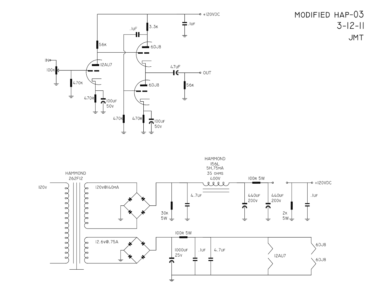
This is a schematic (power supply slightly modified) of the HAP-03 that Radii put out a long time ago. I've some questions about it and would love input regarding some of the passive component value choices.
A few things that stand out to me right away.
powersupply
1. My cap voltage values for the 120v supply are only 200v. I have some 400v caps as well but I'd rather use the 200v caps if I can get away with it, I'm only really concerned about inrush.
2. The Second pi circuit in the 120v supply using a CRC setup is likely totally unnecessary but I'd like to play with it so that resistor will be easily jumperable.
3. Do I even need a pi circuit in the heater supply?
4. I could add a resistor in the heater supply prior to the full wave bridge to dial the heater supply to exactly 12.6v, I'm pretty sure that's a good idea.
amp
1. The cathode bypass caps seem a little on the low side.
2. I have heard (on wikipedia) that a 12au7 wants to see around 100k on it's plate but unless the following 6dj8's grid introduces resistance the 12au7 is only seeing 56k.
3. Is it worth bypassing whatever electrolytic I end up using in the cathode bypass with a .1uf polypro or something similar?
I'm pretty new at this, I've been around for a while but I've only just started actually doing the math (or trying) in order to figure out how this is all working out. I appreciate the patience and help.
Milo
pieter, thanks for the response. I actually have a 250V CT transformer lying around. a 261C6 to be exact, which has a 6.3V filament winding but I could just run the 12au7 in parallel rather than in series. However I have heard this amp and I have liked it, I'm not saying that it is designed correctly but it's interesting that it's not running as hot as it should (a friend at work pointed out the same thing).
Ok so now my "I'm really new at this" comes out. I'd have to recalculate the resistor and cap values for running off a 250V right? Mechanics make sense to me, levers gears and whatnot, electronics are always a struggle a real
Literally I finally got that you design an amp with a specific supply (line level for example) and a specific load (headphones, etc) and that's how you start your math, I was always just staring at schematics wondering how people got from a white sheet of paper to actual passive component values.
Thanks for the help.
Ok so now my "I'm really new at this" comes out. I'd have to recalculate the resistor and cap values for running off a 250V right? Mechanics make sense to me, levers gears and whatnot, electronics are always a struggle a real
The quick answer is that you draw a load line. Then if you don't like t you draw another. One step for me is a Spice simulation. Then a bread board and measure the amp's performance. Each step either refines the design or shows you it can't work and that you have to go back a step or two. I don't think anyone gets it right the first time it is drawn on paper
But the first step to designing any tube amp is to draw a load line. This explains the process in very simple terms.
http://www.freewebs.com/valvewizard1/Common_Gain_Stage.pdf
hello.
have a look at the rectifier(diodes) in the psu, i think they are built in wrong.
greetings
Rectifier diodes are drawn correctly.
56K is fine for a 12AU7 anode load, provided the supply voltage is high enough - yours might not be.
A White cathode follower might be overkill for a line stage, unless you have very long cables. To reduce the risk of instability from a capacitive load, I would add a resistor between the output anode/cathode junction and the 47uF cap - maybe 220-470R? Depending on what you are driving, the 47uF electrolytic could perhaps be much smaller and non-electrolytic?
The second cathode bypass could be a bit bigger. The first one, on 12AU7, is fine.
Plan is to drive headphones most of the time and a chip amp or a discrete Halfler the rest of the time.56K is fine for a 12AU7 anode load, provided the supply voltage is high enough - yours might not be.
A White cathode follower might be overkill for a line stage, unless you have very long cables. To reduce the risk of instability from a capacitive load, I would add a resistor between the output anode/cathode junction and the 47uF cap - maybe 220-470R? Depending on what you are driving, the 47uF electrolytic could perhaps be much smaller and non-electrolytic?
The second cathode bypass could be a bit bigger. The first one, on 12AU7, is fine.
The 47uf Cap on the output I just drew as an electrolytic to remind myself of the polarity in the case that I'd use one. I have a Solen Fastcap for that spot. What's the math to calculate a capacitance match for the driven output. I'm assuming I need level and input impedance of whatever I'm driving and I'm sure there is a formula (Still reading through some of the docs so if it's in there I'm sorry).
Two additions:
1. Headphones I'll drive will always be higher than 220ohm, I only own high-Z cans (this was an accident actually)
2. ChrisA, again that article is just money. It's exactly the noobish structure that I need, really well put and clarifying a bunch of things that always confused me. Thanks again!
Last edited:
What's the math to calculate a capacitance match for the driven output. I'm assuming I need level and input impedance of whatever I'm driving and I'm sure there is a formula (Still reading through some of the docs so if it's in there I'm sorry).
Let's say input impedance of the next stage is 56k.
You already have the 56k at the output of the preamp so the output capacitor "looks" into 28k (2 x 56k parallel).
The math to calculate the capacitance is 1 divided by (2xPixfxr).
In this example 2 x 3,14 x 3 x 28000 = 527788.
1 / 527788 = 0,000001894 (in Farads).
Your output cap should be 2 uF.
That equation looks familiar  .
.
So my two pair of headphones are 220 and 600 ohm respectively, and the chip amp I might power has an input impedance of 22k. The Halfler's input impedance is between 40k and 47k.
Does it makes sense to add a switched resistor to drop the input impedance of the amp when connected to headphones?
.So my two pair of headphones are 220 and 600 ohm respectively, and the chip amp I might power has an input impedance of 22k. The Halfler's input impedance is between 40k and 47k.
Does it makes sense to add a switched resistor to drop the input impedance of the amp when connected to headphones?
A line stage and headphone amp are two different animals, representing two different sets of compromises. I didn't realise you are trying to do both with one circuit.
You could try using two different output capacitors, a high value (electrolytic?) for the headphone socket, and a lower value for the line output. This will avoid having to choose a compromise value. You may need to unplug whichever is not in use, or add a switch at the output.
You could try using two different output capacitors, a high value (electrolytic?) for the headphone socket, and a lower value for the line output. This will avoid having to choose a compromise value. You may need to unplug whichever is not in use, or add a switch at the output.
Pieter, DF - that makes a lot of sense.
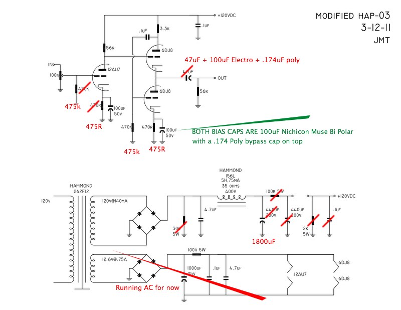
The more I read the more I see that this amp is a pretty huge compromise in it's initial form. Simply drawing the load lines for the input stage was a serious "oh crap" moment. However in reading the article by "the valve wizard" he makes an interesting point about keeping the cathode bypass caps down to as low a value as possible and if available using film/foil instead of electrolytic.
Interestingly enough in the case of the Morgan Jones (headwize amp) the cathode bypass cap is way over valued (in my calculations).
I calculate a bypass cap value for 3Hz at around 100uf, not 1000uf (for the input stage)
Obviously this is a "test, listen, test, listen" situation but does anyone have any insight as to why such high values For C1 and C3 were chosen? Merlin Blencowe makes a specific statement about fully bypassing the input stage in order to reduce possible hum.
Now I can lower the value of the needed bypass cap if I raise the value of the cathode bias resistor to around 2k2, but in order to do that I should bump the anode resistor up to around 100k in order to move my bias around 2V.
It looks like the current schematic suggests that the bias is set to around .75V, which might make sense because of how low the B+ is but it would seem to lack a fair bit of headroom. At the very least I'd like to try the amp as drawn from the manufacturer and then immediately re-biased at around 2v.
maybe I'm getting ahead of myself
The more I read the more I see that this amp is a pretty huge compromise in it's initial form. Simply drawing the load lines for the input stage was a serious "oh crap" moment. However in reading the article by "the valve wizard" he makes an interesting point about keeping the cathode bypass caps down to as low a value as possible and if available using film/foil instead of electrolytic.
Interestingly enough in the case of the Morgan Jones (headwize amp) the cathode bypass cap is way over valued (in my calculations).
An externally hosted image should be here but it was not working when we last tested it.
I calculate a bypass cap value for 3Hz at around 100uf, not 1000uf (for the input stage)
Obviously this is a "test, listen, test, listen" situation but does anyone have any insight as to why such high values For C1 and C3 were chosen? Merlin Blencowe makes a specific statement about fully bypassing the input stage in order to reduce possible hum.
Now I can lower the value of the needed bypass cap if I raise the value of the cathode bias resistor to around 2k2, but in order to do that I should bump the anode resistor up to around 100k in order to move my bias around 2V.
It looks like the current schematic suggests that the bias is set to around .75V, which might make sense because of how low the B+ is but it would seem to lack a fair bit of headroom. At the very least I'd like to try the amp as drawn from the manufacturer and then immediately re-biased at around 2v.
maybe I'm getting ahead of myself
Last edited:
You may be thinking, as many do, that 2 pi R C = 1/f, where R is the cathode resistor. Not so. R is the parallel combination of the resistor and 1/gm.Now I can lower the value of the needed bypass cap if I raise the value of the cathode bias resistor to around 2k2
If you use an electrolytic as a bypass, make it big enough that it does not set the LF rolloff - that job should be done by coupling caps. If you use a non-elec for bypass, then this restriction does not apply.
Valve bias should normally be at least 1V, in order to avoid grid current problems.
I've built a similar circuit (triode connected EF86 DC coupled to a 6922 WCF). It does make a great linestage (with a 1-3uF output capacitor) and a fairly good headphone amplifier. I say fairly good because it won't drive low-z headphones all that well. However with Sennheisers I got some nice results. Pete Millet's "Starving" Student did a better job overall for headphones.
I've got some 1500uf 15v electrolytic rubicons that I could couple to some 10uf solens. I've also got some 100uf 100v electrolytic muses that I could do the same with. Seems like 100uf is plenty, with new calculations. My interest now is the value of the coupling cap, because if it's too low then it's just passing into the electrolytic and not setting the LF rolloff. It would seem (Although I have no math and would love an equation or a link to an article with an equation) that a MKP cap should be of the 1uf value at least.
Last edited:
Finally some updates.
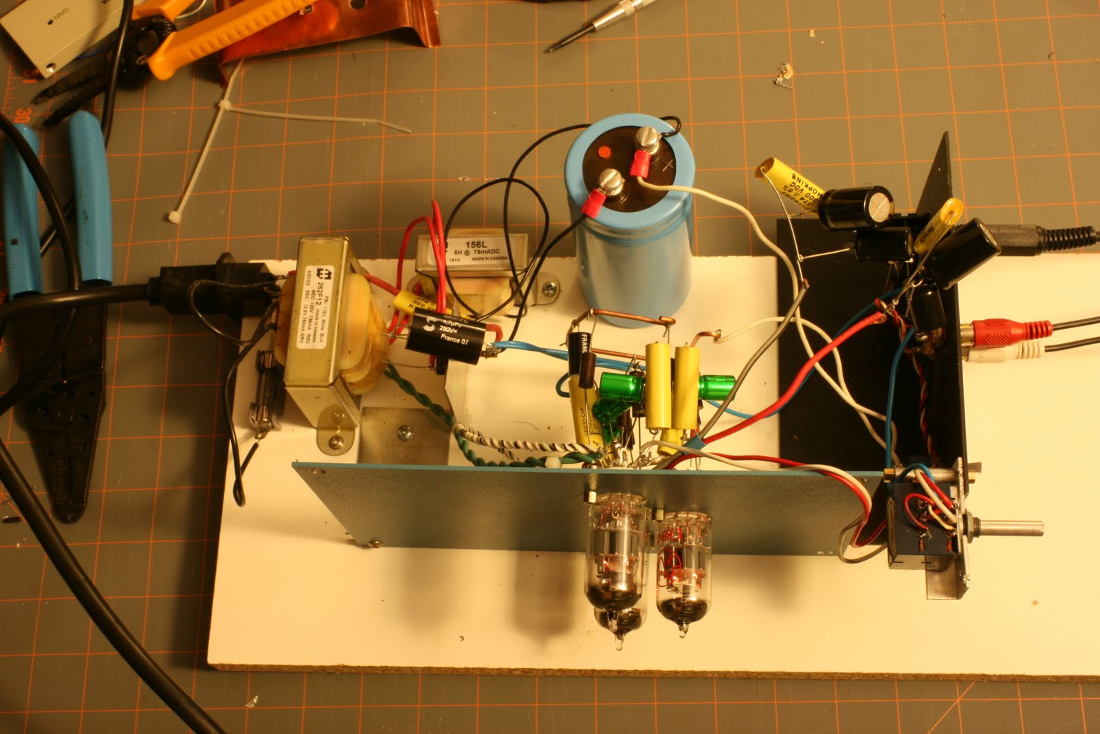

Some things of note.
1. The voltage across the big smoothing cap in the PS is 178VDC.
2. With 250ohm cans the preamp starts clipping at a medium volume
3. There is a bit of hum (which I expected with how long my p2p is.
4. When it's not clipping it sounds quite nice.
5. I want a little more clarity (which I expect to get when I get rid of the electros in on the output.
So with what the voltage is maybe I should rebias the 12au7 higher to try and get more gain and not clip the amp when feeding the cans? Seems to have a harder time with the highs than with bass. Obviously I'm still breaking her in. I have a switch after the big PS cap so I can switch the amp on after letting the filaments warm up a bit. Source is currently a Sansa Clip with my standard test list in FLAC.
Any ideas on how to get the amp to not clip?
Last edited:
- Status
- This old topic is closed. If you want to reopen this topic, contact a moderator using the "Report Post" button.
- Home
- Amplifiers
- Tubes / Valves
- Requesting input on preamp schematic