Why?--Whats wrong with the square as it is....?
Whats with 'Only Allen Bradley' resistors too...?
--Bit 'pretencious' IMO
Personally, IMO, Its a pretty basic scheme, a gain-stage and cathode-follower, and will be quite load imp dependent.....
There's much better schemes out there....
What load you running it into?
Whats with 'Only Allen Bradley' resistors too...?
--Bit 'pretencious' IMO
Personally, IMO, Its a pretty basic scheme, a gain-stage and cathode-follower, and will be quite load imp dependent.....
There's much better schemes out there....
What load you running it into?
Please post a capture of a 100Hz square wave loop back test through just your data acquisition hardware.
What is the load impedance you are driving with the output of this thing? What does it look like into higher impedance loads? Is the response affected by the value of that coupling capacitor? If you are driving an 8 ohm load it is unlikely that the coupling capacitor has sufficient capacitance to pass the 100Hz square wave undistorted because the time constant formed with the load and source impedance is too short, this means you need more capacitance or a higher load impedance. Or you can ignore it if the bass performance is sufficient with your headphones since music isn't square waves.
See this, it may help you to visualize what is going on better even though it relates to transient vs steady state behavior in a series RC network:
Technical Paper #1: Square Wave Response of a Series RC Circuit
FWIW I have never understood the mystique around Allen Bradley carbon comp resistors, they are lousy resistors compared to almost anything made these days. Lots of excess noise (no I'm NOT talking about Johnson noise) when you run dc current through them and a significant voltage coefficient which is fine if you like unnecessary distortion generators in the signal path.. (These resistors can be up to 20dB noisier than a good NI WW..) Two watt versions are admittedly a lot better than the 1/2W in both respects, but still.. A nice non-inductive Mills WW has neither of these faults, nor do most metal films to an appreciable extent.. A matter of taste I suppose..
Last edited:
FWIW I have never understood the mystique around Allen Bradley carbon comp resistors said:Im not using Allen Bradley, i have ordinary cheap ressistors. Output capacitors are Siemens. Honestly i have never heard how Allen Bradley sounds. But I dont believe that there is some magic. Yes it could be a matter of taste")
And do not forget to set your 'scope in "DC"
Im not using a scope but software. In loop mode the sguare is ok.
What is the load impedance you are driving with the output of this thing? What does it look like into higher impedance loads? Is the response affected by the value of that coupling capacitor? If you are driving an 8 ohm load it is unlikely that the coupling capacitor has sufficient capacitance to pass the 100Hz square wave undistorted because the time constant formed with the load and source impedance is too short, this means you need more capacitance or a higher load impedance. Or you can ignore it if the bass performance is sufficient with your headphones since music isn't square waves.
Upppsss.. i forgot the load ressisor on the output of preamp, the input ressistance of PF99 should be 47K. So, to test the preamp it means i should put a 47K on the output?
Upppsss.. i forgot the load ressisor on the output of preamp, the input ressistance of PF99 should be 47K. So, to test the preamp it means i should put a 47K on the output?
You need to place a load on the output representative of what you are driving with it, if not headphones then whatever the input impedance of the device you normally drive should be used.
You might want to take a look at your power supply as well - if you are driving anything above 1K input impedance the square wave response at 100Hz should be pretty close to perfect, if it's not you need to look at the coupling cap first - do you have the 200uF shown or something less? Then look at the supply and make sure you don't see a 100Hz square wave on the supply - if you do more supply capacitance is needed. You should use a scope for this or make sure your data acquisition hardware is designed for high voltage use.
One other thought is that if this is being used only as a line stage you can completely remove the second stage as the rp of the 5842 is only a little over 1K so this should be fine for driving a power amplifier directly. I'd use a 1.0 - 2.2uF coupling cap which should be sufficient for an input impedance of 47K. Should sound better..
Last edited:
You need to place a load on the output representative of what you are driving with it, if not headphones then whatever the input impedance of the device you normally drive should be used.
You might want to take a look at your power supply as well - if you are driving anything above 1K input impedance the square wave response at 100Hz should be pretty close to perfect, if it's not you need to look at the coupling cap first - do you have the 200uF shown or something less? Then look at the supply and make sure you don't see a 100Hz square wave on the supply - if you do more supply capacitance is needed. You should use a scope for this or make sure your data acquisition hardware is designed for high voltage use.
One other thought is that if this is being used only as a line stage you can completely remove the second stage as the rp of the 5842 is only a little over 1K so this should be fine for driving a power amplifier directly. I'd use a 1.0 - 2.2uF coupling cap which should be sufficient for an input impedance of 47K. Should sound better..
First I like to thank You for Your reply
Maybe My mistake was the fact that i didn't used any output impedance load (instead of input of my sound card), can I add also an ressistor of 1K on the output of preamp?
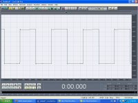
Yes I have a 200uF on the output of catode follower stage. 2 caps of 100uF in parallel. About power supply I have, after rectifier tube 2x50uF then a choke in series and after 4x68uF/350V ROE caps. The preamp output without input signal is perfectly quiet. I dont have an oportunity to use a scope still. Im using my PC and CoolEdit software for generating tones. The output of preamp is connected on input of my sound card and input of preamp to output of the sound card. Im generating tones and recording them, then i play the recorded signal by Nero ShowTime. In loop mode without preamp, the signal responce is ok.
I've tried to skip the catode follower stage and to use just gain stage (the gain stage is PCC88 in my case) with 1uF on the anode. The responce on 100Hz was the worst in this case (I measured the unloaded output-the only load was the input of my sound card).
The other person also suggested me to skip that second stage. I think that the catode follower stage is essencial for driving SE Power Follower amplifier (gain - 0) because of lowering the impedance.
I achieved some improvement on 100Hz square responce removing the decoupling cap and catode ressistor of gain stage. Instead of im using red-led biasing. But the responce is still far from perfect.
With red-led biasing sound improved, basses are more tight, I think the reason for that is small improvement on 100Hz square responce.
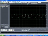
After I increased the input level signal the responce look like this:
responce on 100Hz square signal
Also i will apriciate any suggestion how to skip the catode follower stage and use just a gain stage. I know i should add an capacitor on anode of first tube...and what else?
responce on 100Hz square signal
Also i will apriciate any suggestion how to skip the catode follower stage and use just a gain stage. I know i should add an capacitor on anode of first tube...and what else?
Attachments
After I increased the input level signal the responce look like this:
responce on 100Hz square signal
Also i will apriciate any suggestion how to skip the catode follower stage and use just a gain stage. I know i should add an capacitor on anode of first tube...and what else?
Could you run this test again but 6-10dB lower level? That trailing edge 'hook' bothers me. Are you just clipping out the ugly stuff or is post #3 what it is at lower level?
G²
Could you run this test again but 6-10dB lower level? That trailing edge 'hook' bothers me. Are you just clipping out the ugly stuff or is post #3 what it is at lower level?
G²
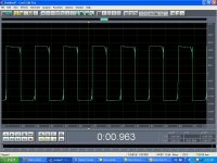
The last test was on -6dB. It looks better then responce on post #3.
The responce on post #3 was with lower input signal to the preamplifier. Im confused why its like that also.
The last test was on -6dB. It looks better then responce on post #3.
The responce on post #3 was with lower input signal to the preamplifier. Im confused why its like that also.
It looks like its just clipping. What is the output level in Volts p-p?
Run the test several times reducing the level 1 dB each time. It might be quite revealing. Can you generate a triangle wave and run that into the amp?
G²
What sort of person takes a bog-standard circuit and calls it "no compromise"?
As in so many circuits I see, this one suffers from the "I trust my wiper will never leave the track" syndrome. That is a compromise.
The square wave in post #12 seems to show slew-rate limiting and oscillation, on the negative-going edge. I think the CF is cutting off (so the cathode resistors have to drag the voltage down) then switching on messily.
What sort of person takes a bog-standard circuit and calls it "no compromise"?
As in so many circuits I see, this one suffers from the "I trust my wiper will never leave the track" syndrome. That is a compromise.
The square wave in post #12 seems to show slew-rate limiting and oscillation, on the negative-going edge. I think the CF is cutting off (so the cathode resistors have to drag the voltage down) then switching on messily.
Its design of Andrea Ciuffoli, so He is the person
Can You suggest some better circuit for preamp? I need something to drive the Power Follower SE "amplifier" (no gain)
It looks like its just clipping. What is the output level in Volts p-p?
Run the test several times reducing the level 1 dB each time. It might be quite revealing. Can you generate a triangle wave and run that into the amp?
G²
Ill do what You seuggested. I have to check if that software can generate a triangle wave.
- Status
- This old topic is closed. If you want to reopen this topic, contact a moderator using the "Report Post" button.
- Home
- Amplifiers
- Tubes / Valves
- 100Hz square preamp responce help