Hi, this is my first post so please excuse me if I make a few mistakes. I have had my MC 10L for about two years and I have been really pleased with it until a few weeks ago. My amp suffered from a similar problem that has been related a number of times on this site, and that was the sparks, smoke and loss of sound from the left channel. I turned it on and while waiting for it to warm up I heard a crackling from the left speaker and then saw smoke from around valve 1. I checked diyAudio site and read up on what was the likely problem and what to check. Well I removed the cover from the amp and sure enough the cathode resistor from valve 1 had burned pretty badly and the valve had a bit of carbon at the base. I replaced the two cathode resistors on the left side and ordered two new valves. I have done checks to confirm the voltages in the empty valve holders and they are negative 35v and 450v as specified. I installed the valves and turned it on but still no sound from the left channel. I have checked the bias on all 4 valves and they are set at .35v or as close to that figure as I can get. While I had the cover off I have closely checked all the wiring connections with a magnifying glass and inspected the capacitors and resistors for any obvious signs of damage. I have not noted any and no "burnt" smells emanate from within.
Any suggestions as to what my problem could be? What further checks can I carry out. I have a terrible feeling that it could be the output transformer although I have no way of checking. Incidentally I have 240v transformers, or at least that was what was ordered and stamped on them. Any suggestions would be greatly appreciated.
Please note that I am also very new to valve amps and have limited knowledge, but I am keen to learn.
Mike.
Hi, Mike!
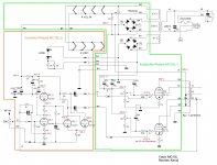
You can check primary coil of output transf. There is two primary coils with middle point, that goes to +U.
1. Check resistance between middle point and every end, that goes to plate of every tube. Results must be the sames.
2. Check all resistance between plates in both channels.
/don't forget to switch off the amplifier!!/.
3. You can put new cathode resistors, switch on the amplifier and measure every cathode potential before some smoke.
4, You can measure every first grid potential of every tube.
5. You can change interstage capacitor to some similar new capacitor, that goes from prestage to bad tube and see what will happen.
6. Or You can disconnect interstage capacitor from first grid of bad tube and measure grid potential.
It must be the same like on another output tubes.
http://pdf1.alldatasheet.com/datasheet-pdf/view/87904/PHILIPS/EL34.html
/It's very hard to burn tube..../
Last edited:
Check your speaker lines too as an open circuit will cause flash over in the output valves if you are driving the amp at the time. The presence of a carbon track is one that I have observed on guitar amps brought in for repair here where the speaker(s) were accidentally unplugged whilst the guitarist was playing. Worth a check.
Sorry for my bad English and mistake....I mean, interstage capacitor maybe is licking and grid potential is positive, and tube is overloading.Sorry....p.6: You can measure all grid potentials of tubes and compare, maybe interstage resistor of bad tube is licking.....
Check your speaker lines too as an open circuit will cause flash over in the output valves if you are driving the amp at the time. The presence of a carbon track is one that I have observed on guitar amps brought in for repair here where the speaker(s) were accidentally unplugged whilst the guitarist was playing. Worth a check.
That's both external and internal lines by the way. You could have a very high resistance connection that was capable of you hearing cracking from the speaker but it was high enough to do damage. If you do not have a multimeter (the best way of checking) you could use a single AA cell in series with a speaker line. i.e. undo one speaker connection from either of the rear terminals, then place a AA cell (either way round) between the wire taken off and the terminal from whence it came. You should hear a healthy crackle as you touch the wire on the cell. A bit of a crude method but should prove circuit continuity through the speaker and secondary winding of the output transformer. Don't do this with the amplifier switched on though
") .
.Many thanks to azazello, Helmuth and Hi-Q for your suggestions. I have done some further checks as suggested and it looks like the output transformer is OK. Hi-Q i used your crude battery test and I got a good healthy crackle and my multimeter shows 8 Ohms in both right and left channels. I suppose that means I have an issue with one or more capacitors. As you can probably guess I don't have any capacitor tester so I was considering replacing some or all of the capacitors. Suggestions as to which one/ones are most likely to have failed. Again as a novice could you help me by identifying the capacitors by value. Or alternatively I have copied that handy little document "A LOOK AT THE YAQIN MC-10L" and you could refer to that. As you can see I am very new to this game but I am getting better.
Regards, Mike.
Regards, Mike.
Just for interest, if you ever take the base plate off (a mission I know!), take a look at those joints to earth around the output tube sockets. An example is shown in my document you mention. I came across this possible problem on my Amp whilst I was doing the screen resistor modification. I found taking the base plate off was best done after laying the amp down on its top side so that the transformer cans made everything stable.
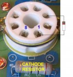
I made a note of which screws went where as I removed each one so that re-assembly was no problem. Once removed, access to the underside of those EL34 sockets is a cinch. I dread anything happening to the main power board though, I actually managed to get to all of the print once but I would not like to do it again! Mike, only the coupling capacitors should give you any cause for concern but I doubt they are at fault in your case as the negative bias voltage seems OK. Do the voltage checks again on the empty sockets (taking the usual care!) and also check you have 10 Ohms from cathode pin to ground and that pin 1 is connected to pin 8 (pins located either side of the spigot).
I would also suggest moving over the tubes from the working channel to see if that helps, I am still hoping for feedback on owners concerning the slight possibility (and I say slight possibility) of failure of the screen grids due to the absence of a resistor. Controversy reigns here as some say the resistors are to prevent spurious oscillation and improve stability while others say it is there to protect the screen from passing too much current and actually failing. There's probably truth in both arguments. Hope you have some luck with your problem and let us know how you get on.
Les
Les thanks again for your response. As suggested I swapped the tubes from the right channel that was working well but no joy. Right channel still works but no sound from the left channel. I have again checked the voltages on the valve holders at tube 1 and tube 3 and have confirmed the following for both: pin 5 -35v, pin 3 460v, pin 4 460v. Pins 1 and 8 show 10.5 Ohms and both are connected. Both cathode resistors show 10.5 Ohms as well. I have previously looked at the solder joints on all the pin connections (I removed the bottom cover to access all the circuit boards to enable a close inspection with a magnifying glass) and I was unable to identify any suspect looking joints. While I had the bottom cover off I looked at all the capacitors and resistors for any visible signs of damage but could find none. Having read on this forum a number of times about similar problems, some even causing more damage, I was expecting to simply replace a couple of cathode resistors and tubes and I would be back in business. It is frustrating to get to the stage where the obvious damage has been repaired but it is still 'broke'. I am prepared to replace the capacitors but I am having a little difficulty in obtaining exact replacements for the ones in the left channel so I presume any replacements will have to be both channels to ensure like sound and performance as not all capacitors are equal. What would best, replace all or progressively replace those on the left channel to see if it is successful? Fortunately I have the time as I am now retired, but I was looking forward to listening to my tube amp rather than fixing it. Where to from here? As the weekend approaches perhaps a wee dram of Lagavulin and a bit of a think might be in order.
Regards Mike.
Regards Mike.
I think somehow you have to discover if the fault lies in the output stage or loss of signal from the input stage. It is a pity the left and right interstage connecting cables are not long enough (unless you are lucky) to allow cross coupling, which would be nice to do in the absence of an oscilloscope.
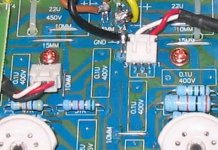
The first picture shows the left and right signal lines/connectors with Red and White wires.
With power removed from the amp, pull the power tube V3 and measure the voltage on pin 3 with respect to chassis earth. My amp had been off for 24 hours yet there was 60V still lurking on there. By placing a 1k resistor between pin 3 and chassis, it produced a very large crackle in the speaker and you should obtain the same, it will prove the output transformer to speakers has a good chance of being OK. Don't try this if the voltage on pin 3 is much higher than this!
Not only would you would have to use a much higher value resistor but it would be too dangerous to recommend!
If the voltage is close to zero, you could use an AA cell again connected between chassis and pin 3. You should hear a slight crackle as the HT line charges up to 1.5V via the left hand output transformer. It will stop crackling once the 1.5V is established but crackle again when the 1k resistor is applied until the 1.5V is depleted. Not a very exotic test method by any means but simple enough in trying to exonerate the output circuit without test gear. But you must take the necessary precautions due to the possibility of 450V lurking here under fault conditions. If your multimeter says there is no voltage, don't trust it, check the multimeter is working correctly and your connection points are correct before believing it. If you find the output seems to be OK then you may be looking at a fault in the phase splitter or input circuits.
All this should be done with no power applied.
Anyway, the purpose of this post is to try and get you to isolate the faulty stage a bit more then we can take it from there.
Attachments
Les, it must be my lucky day. The right interstage connecting cable was indeed long enough to connect with the left output stage and sure enough I have sound from the left channel. Am I correct in assuming that my problem lies within the input stage? I have turned my attention to the 6N1 valves and they appear to glow. I changed the valves on the left with two I had as spares but no joy. Incidentally valve 1 on the left of the front end created a sound when I accidently bumped it. A light tap on the other valves failed to give any similar sound. It make no difference what valve I place in the 1 valve holder they all make this noise in the left hand speaker. Don't know if it means anything but I thought I would mention it. Please excuse my dumb questions but I am still coming to grips with these things electronic I am more familiar working on my old mechanical monsters (MG and Mini). I suppose this now leads me back to capacitors as being at fault? Your assistance is greatly appreciated.
Regards, Mike.
Regards, Mike.
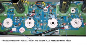
Great Mike, we are getting somewhere. Can you try removing the plug from XS201 and insert into the board connector the plug from XS205. If this restores signal then you have a fault in the Left hand input wiring somewhere. If the sound is still missing then it leads to a fault in the pre-amp section. Going by your initial fault description it should more probably be due to a fault on the pre-amp section. Either the coupling capacitor was bad and now open circuit (hard to imagine) or you have lost voltages somewhere on the input stages. In the attached, V1 is the input valve and V2 is the phase splitter. Try the plug swap first and get back. Les
P.S. with respect to the valve noise from V1, this is probably micro phonics and could be telling us that all is well there as there must be gain/sensitivity here. This makes an input or input wiring fault more of a possibility and discounts any problems with the coupling capacitors.
P.S. with respect to the valve noise from V1, this is probably micro phonics and could be telling us that all is well there as there must be gain/sensitivity here. This makes an input or input wiring fault more of a possibility and discounts any problems with the coupling capacitors.
Attachments
Last edited:
Yes Mike, it's late here, 2.30 AM should have been in bed hours ago!
Sorry for that socket number error, indeed it was XS202. But the good news must be that the fault is in the input wiring or around the switch. Have you checked the inputs on the rear panel?
It could be that the original fault was a defective output tube and the loss of sound a secondary fault due to poor input connection. The last page of my guide detailed a problem due to wire whiskers near the switch board, might be worth a check. The whiskers are very fine so easily missed. At least the majority of the amp seems to be OK, very pleased for you on that and no major damage like output transformer trouble. Your multimeter should be able to check for short circuits and continuity. All the Best, Les
should have been in bed hours ago!Sorry for that socket number error, indeed it was XS202. But the good news must be that the fault is in the input wiring or around the switch. Have you checked the inputs on the rear panel?
It could be that the original fault was a defective output tube and the loss of sound a secondary fault due to poor input connection. The last page of my guide detailed a problem due to wire whiskers near the switch board, might be worth a check. The whiskers are very fine so easily missed. At least the majority of the amp seems to be OK, very pleased for you on that and no major damage like output transformer trouble. Your multimeter should be able to check for short circuits and continuity. All the Best, Les
Here is the copy, my memory is getting worse as the problem was due to metal shards on the RCA socket board. Grey matter aside Mike, the problem was also on the Left channel, has lightning struck twice?
From audiokarma.org member TonyMc.
I have been having an issue with my Yaqin since I bought it that I finally figured out last night. I noticed that the L channel would cut out once in a while. I thought it was a bad cable so I swapped it out and all was well until last night it did it again. So now being a bit more concerned I took the amp to the ol' work bench and opened it up. I looked at the RCA in-puts and all looked well. The R and L sockets are one unit on a black plastic block then soldered to a small circuit board and plugged into a couple of nice computer style cables, all very clean. The layout of the amp looks very nice so I could not figure out what the problem was. Then I saw what looked like a hair sitting in the chassis. Low and behold it was a piece of metal from the manufacturers putting the small machine screws in the aluminium side rails. I found a couple more and then a couple more so I grabbed a small light to shine under the RCA circuit board and what do you know... One of those little shards of aluminium was touching the little pin for the L RCA tuner jack that comes out of the bottom of the circuit board.
So far all is well since removing all loose shards.
Les.
What can I say other than many many thanks. azazello I thank you too and apologise for not responding to your second message more quickly. I got all excited when I started getting some results from the tests recommended. My problem has been fixed and I can't thank you enough. I have visited this site a number of times previously just to see what was going on and I noticed that it was a community with a wealth of knowledge that they were unselfishly willing to share. This been clearly demonstrated by the responses I have received in trying to fix the problem with my amp. I have to especially thank Les, because he has been fantastic. As I explained I was a bit of a goose when it came to tube amps but with his guidance I was able to sort out the problem. How good is that? Les hopefully we can continue some dialogue on an obviously shared interest of audio. So from a very happy person from the "colonies" thanks once again. I am hooked on this site and who knows one day I may be able to reciprocate.
Regards, Mike.
Les.
What can I say other than many many thanks. azazello I thank you too and apologise for not responding to your second message more quickly. I got all excited when I started getting some results from the tests recommended. My problem has been fixed and I can't thank you enough. I have visited this site a number of times previously just to see what was going on and I noticed that it was a community with a wealth of knowledge that they were unselfishly willing to share. This been clearly demonstrated by the responses I have received in trying to fix the problem with my amp. I have to especially thank Les, because he has been fantastic. As I explained I was a bit of a goose when it came to tube amps but with his guidance I was able to sort out the problem. How good is that? Les hopefully we can continue some dialogue on an obviously shared interest of audio. So from a very happy person from the "colonies" thanks once again. I am hooked on this site and who knows one day I may be able to reciprocate.
Regards, Mike.
Mike, what was the fault?
Thanks
Andrew, also with a dead mc-10l
- Status
- This old topic is closed. If you want to reopen this topic, contact a moderator using the "Report Post" button.
- Home
- Amplifiers
- Tubes / Valves
- Yaqin MC 10l problem