In my mini-console project I will be using two chassis, one for preamp and one for power amp and PS. On the guitar amp I built (single chassis) I used a two star arrangement with the filter and power tube grounds being returned to a spot on the chassis near the PT and the other signal grounds returned to a spot on the chassis near the input jacks. This worked quite well but with two chassis it seems like it is a little more complicated.
Unlike the guitar amp I am using a can cap for the PS filter. Here is what I have in mind.
1. Connect safety ground of power cord to the chassis at the entrance point.
2. Create isolated star for each stage and run a single ground wire from each (and the input jacks) back to a single chassis connection point on the power amp chassis right next to the can cap.
3. The signal ground from the preamp would not be connected to the preamp chassis at all but brought back to the PA chassis star via. the umbilical cord.
4. A safety ground connection will be brought back from the preamp chassis directly to the safety ground connection on the power amp chassis.
Does this sound like a good plan.
Another practical question. To solder the can cap ground (case tab) to the chassis will I need to purchase a soldering gun or is it possible to safely do it with a propane torch? I know it sounds ham fisted but my thought is to carefully heat the chassis and make a small pool of solder at the tab location, then push the can cap onto the chassis (and thus the tab into the molten solder) and then remove the torch flame (within a second or so to avoid over heating the cap). Stupid idea?
Would it be correct to assume that just securing the can via the twist tabs and soldering a ground wire (that is attached to the chassis) to a tab is inadequate?
In my mini-console project I will be using two chassis, one for preamp and one for power amp and PS. On the guitar amp I built (single chassis) I used a two star arrangement with the filter and power tube grounds being returned to a spot on the chassis near the PT and the other signal grounds returned to a spot on the chassis near the input jacks. This worked quite well but with two chassis it seems like it is a little more complicated.
Unlike the guitar amp I am using a can cap for the PS filter. Here is what I have in mind.
1. Connect safety ground of power cord to the chassis at the entrance point.
Link this to the star Ground! from PSU to each star point.
2. Create isolated star for each stage and run a single ground wire from each (and the input jacks) back to a single chassis connection point on the power amp chassis right next to the can cap.
I would keep any power amp and pre-amp sections with their own star and connect each to it's own ground connection. This would then be connected to the safety ground!
3. The signal ground from the preamp would not be connected to the preamp chassis at all but brought back to the PA chassis star via. the umbilical cord.
The noise level in the power amp chassis is greater than the pre-amp chassis ground due to current and leakage!
So you may get a difference in potential between your signal ground and pre-amp chassis ground!
4. A safety ground connection will be brought back from the preamp chassis directly to the safety ground connection on the power amp chassis.
It is mandatory that all chassis have a ground connection. Each star point should go to one star safety ground connection. These should go to the main safety ground!
Does this sound like a good plan.
Another practical question. To solder the can cap ground (case tab) to the chassis will I need to purchase a soldering gun or is it possible to safely do it with a propane torch? I know it sounds ham fisted but my thought is to carefully heat the chassis and make a small pool of solder at the tab location, then push the can cap onto the chassis (and thus the tab into the molten solder) and then remove the torch flame (within a second or so to avoid over heating the cap). Stupid idea?
The can may explode! Secure the can with a strap and connect with wire!
Would it be correct to assume that just securing the can via the twist tabs and soldering a ground wire (that is attached to the chassis) to a tab is inadequate?
Use a strap to create a mechanical support! Or Ty base and ty-rap.
Just a few thoughts.
Regards
M. Gregg
Last edited:
Again I assume a US tech will add to this!
Safety is the number one issue. ie no differences in potential between chassis.
Then ensuring no current ground loops.
The resistance between grounds must not interfear with automatic disconnection of supply under fault conditions.
Any cord connections that are removable should be fitted with a plug socket with live supply breaks first before ground.
Regards
M. Gregg
Last edited:
Thanks guys.
M. Gregg, Am I understanding correctly that you are saying to connect the grounding star in the preamp chassis to that chassis and then connect that chassis' ground to the main ground connection on the main (power amp) chassis?
Also is a mechanical connection of the can cap to the chassis and a separate electrical connection OK or do I need to make the mechanical (clamp) connection the only electrical connection?
Thanks guys.
M. Gregg, Am I understanding correctly that you are saying to connect the grounding star in the preamp chassis to that chassis and then connect that chassis' ground to the main ground connection on the main (power amp) chassis?
Yes, If you dont - a difference in potential can exist under fault conditions between output ground and chassis ground.
When you test you may may need to have a ground connection on only one end of the screen on any interconnects. This is still preferable to relying on cable screens for safety connections to ground!
An example of this is getting a short to ground on the preamp as you pull a cable plug and socket apart to find yourself becoming the connection to ground between preamp fault and PSU ground! (cable in one hand and chassis in the other).
Ensure ground cables can carry any fault current ie fuse ratings and cable size.
Also is a mechanical connection of the can cap to the chassis and a separate electrical connection OK or do I need to make the mechanical (clamp) connection the only electrical connection?
Yes, the can of the cap needs a mechanical fastening, This can be insulated from the can if you wish then electrical connection with wire. Most caps have the ground tab connected to the can or it is insulated from connections. You can check with a meter.
Regards
M. Gregg
Thanks, the safety issue is clear to me now.
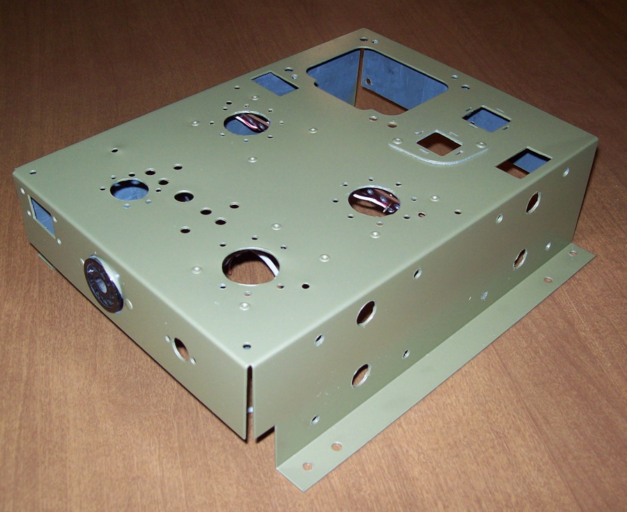
The style can that I have has the four "ears" that go through the chassis and are then twisted to secure it. Normally I have seen these with one of the ears soldered to the chassis to make the electrical connection. There are two places on the chassis where one of these cans can be installed. One is cut right in the metal of the chassis and the other is an insulator (some kind of fiber) which is attached to the chassis. I could easily mount to the insulator and then run a wire to the desired ground point but the insulator is closer to the output tubes than the other mounting point and I would prefer as much space as possible to keep the cap cool. That is why I was wanting to use the direct to chassis connection.
You can see the two mounting choices here...
I would suggest that some of M.Gregg's advice could be modified a bit.
Given that the preamp chassis has hazardous voltage on it (but not primary side mains) and the main amp uses a commercial power transformer, then a plug-socket connection between main and preamp chassis would be acceptable, as long as all the connection terminals were shrouded and a hazard sign added, and the caps in the preamp chassis discharge within 60 seconds of the connection being pulled. There would be no requirement per-se to have a PE (protective earth) connection to the preamp chassis, but there would be a practical need to electrically connect the preamp chassis to the main amp chassis to extend the nominal earth screen shielding.
The circuitry in the preamp is best made floating, with the preamp star 0V being connected (via umbilical cable) back in the main amp at the local star ground point of the next signal stage (which may not be chassis ground if that is placed closer to the power supply or speaker socket). If shielding is used in the umbilical cable then it should be connected to the 0V star points at either end.
The PE from the mains cord should be a separate chassis connection from any other ground/chassis connection. It should not be the amp star ground point to chassis.
Only make one 0V ground connection to chassis. Many prefer to do this at the input socket(s), but I find that practical influences can dictate other positions, such as at speaker output jacks, or at an output stage / main filter cap point (as per your filter cap mounting issue). Use a distributed star ground scheme daisy chaining out from that point. (ie. your original guitar amp with two chassis connection points is not as effective as a single point scheme).
Ciao, Tim
Just a point of interest.
In the UK if a system is extended into another enclosure wheather that extention is mains or an extention of the electrical system voltages (which may under fault conditions become dangerous) that enclosure must be at earth potential. You cannot rely on a connection using part of the other chassis to provide continuity of protective earth.
However this may not be the case in other countries.
Regards
M. Gregg
A point I may not have made clear is that even though these are separate chassis they will both be in the same wooden enclosure (console) and only the preamp chassis will be available to the touch unless the back is removed.
I don't have a close up of my cap but it is like this one except it is 3 section.
CE - USA 30µFx20µFx20µFx20µF / 525V
Here is the chassis before painting with the cap on it.
I don't have a close up of my cap but it is like this one except it is 3 section.
CE - USA 30µFx20µFx20µFx20µF / 525V
Here is the chassis before painting with the cap on it.
M.Gregg is correct that the best action to take is to provide a permanent protective earth connection between the two chassis. The standards are a minefield of if's and buts when it comes to DC voltages and protective earthing, so to keep it simple just make a proper cable connection as you would the earth connection from the mains cord.
One can also run in to compliance hassles with capacitor energy storage. The standard I was just cross checking (iec60950) wants 1 second or 10 second time constants on hazardous voltage level caps if you have removeable hazardous power connections. It changes if you have fixed wiring.
One can also run in to compliance hassles with capacitor energy storage. The standard I was just cross checking (iec60950) wants 1 second or 10 second time constants on hazardous voltage level caps if you have removeable hazardous power connections. It changes if you have fixed wiring.
Looking at the caacitor, I have worked on these in the past.
You push the tags through the holes in the chassis and twist. The problem with them is that no matter how well you twist the tags they come loose and rock side to side and twist. This brakes the wires off the connections over time. So people solder the tags- then when they blow or go dry you cannot get them out. So they solder one tag- this brakes off with the rocking motion. The way around this is to mount with the twist and slip a standard through hole mount over the top bolt to chassis. (the ring that goes around a standard cap and the tags bolt to chassis). The tags if I am correct should earth the can to the chassis that go loose!
Hope this helps!
Regards
M. Gregg
- Status
- This old topic is closed. If you want to reopen this topic, contact a moderator using the "Report Post" button.
- Home
- Amplifiers
- Tubes / Valves
- Two chassis grounding