I realize that being a newbie my first post was quite generic in my question of amp suggestions. So iv done a little reasearch and have decided id like to attempt to build an amp from the marantz 8b schematic or one from the kta- hifi pcb. I like the idea of building from a pcb but iv heard the st-70 is a little lacking in sound quality. Although parts wouldn't be such an issue. As far as the 8b gose I guess my question is.. am I going to be hard to find the parts I need? I hear that the 8b has excellent sound.
Any help is apreciated. Thanks, paul
Any help is apreciated. Thanks, paul
Are you planning to build an ST-70 type amp using chassis and transformers from someone like dynakit? If not there are certainly other transformers that are significantly better performers than the stock Dynaco transformers.
In triode connection though they are surprisingly decent performers, and the amplifier sounds quite nice.
The parts required for the driver board are readily available from Mouser, Digikey, and Michael Percy audio consultant. I recommend metal film resistors and good coupling caps. (Clarity ESA, REL PPFX or better, etc.)
Power supply improvements are always worthwhile as well.
Yeah, I'm the guy behind KTA. (The board is licensed to Geek who currently offers it.)
Kevin,
Wow no one better to talk to than the guy who designed the board. Ill actually be fabricating my own chassis as I'm a metal fabricator by trade and it will be no problem to get a hold of a good sheet of aluminum (I'll probably frame it with wood). I would like to upgrade as much as possible (as cost allows). The only thing I'm concerned about is the output in triode operation. Thats about half the power of the regular operation right? the speakers I'm building this amp for ask for 50wpc. They are actually very efficient for their size (Frazier sevens).. I might need more power..
Wow no one better to talk to than the guy who designed the board. Ill actually be fabricating my own chassis as I'm a metal fabricator by trade and it will be no problem to get a hold of a good sheet of aluminum (I'll probably frame it with wood). I would like to upgrade as much as possible (as cost allows). The only thing I'm concerned about is the output in triode operation. Thats about half the power of the regular operation right? the speakers I'm building this amp for ask for 50wpc. They are actually very efficient for their size (Frazier sevens).. I might need more power..
Last edited:
quote:
Are you planning to build an ST-70 type amp using chassis and transformers from someone like dynakit? If not there are certainly other transformers that are significantly better performers than the stock Dynaco transformers.
In triode connection though they are surprisingly decent performers, and the amplifier sounds quite nice.
I have the opinion that the transformers on the Dynaco stereo 70 are fine. One thing about this hobby is that you can get hung up on spending way more money than you need to to achieve a desired goal. The dynaco transformers perform well. Is it worth spending hundreds of dollars extra on the gamble that it might perform better sound better? In my opinion one has to draw a line somewhere. Triode in my opinion is a myth. It sounds ok as is and maybe just maybe a touch sweeter in triode depending on the program one is listening to. Install a quad pole double throw switch in the mix so that you can run it either way. Do not however flip the switch when the amp is powered up.
As one who has used a number of different driver boards I would highly recommend the Dynamutt or the Mapletree driver board over the KTA board. Yes, I have used the KTA board also.
If you want triode power don't forget Pete Millet's amp. 20 to 250 watts channel depending on iron and tubes chosen. I've just fired my my second compactron amp, kinda simplified version of Pete's. Its set up for 40 watts/channel triode mode, and it can chase you out of the room........ Pete's board is around $50 and gives Dynaco a run for the money!! The ST70 can be heavily modified, power supply, driver board, triode mode, don't forget different iron choices....All it co$t$ i$ a little $$
If you want triode power don't forget Pete Millet's amp. 20 to 250 watts channel depending on iron and tubes chosen. <snip>
This ought to be a pretty good option as well. Pete's stuff tends to be well thought out, and the boards are well made.. (I've not tried this particular board)
The KTA design is over 23yrs old now and hasn't changed at all in that time, it's a bit old school in terms of its design and was designed at a time when the supply of better suited small signal tubes seemed questionable. (Pre-internet) Assembled boards came with Solen coupling caps as a result of needing to keep costs low - these more than anything else could stand replacement with something better. (The assembled and tested board sold for just $79 in 2001 the last year I offered it directly.)
IMHO I found the difference between A-431 tOPT riode connected as opposed to UL to be quite significant and I strongly preferred triode connection. This may be a function of what I was listening for at the time as well as the speakers I was using. What little I remember of actual measurements was that the distortion spectrum in triode mode was much less extended than in UL mode.
but iv heard the st-70 is a little lacking in sound quality.
I just want to make sure you realize that that commonly held opinion is referring only to the stock original circuitry, which is completely replaced by all the various driver boards available -- including Kevin's KTA board. The reason they all exist is due to that opinion, and the fact that the rest of the components form a pretty decent foundation to build upon.
They all sound different from the original ST-70 circuit, and from each other. The only thing common to them all (or at least most of them) are the power supply and output sections.
Have fun.
")
..Todd
Last edited:
iglehart332;2491402} I like the idea of building from a pcb but iv heard the st-70 is a little lacking in sound quality.[/QUOTE said:I've owned a totally stock 1961 build ST70 and just put new electrolytic caps and output tubes in it. Has fabric insulation transformers, I've owned it since 1970. I has the original 7199 dyna circuit with 1970 RCA 7199's. The new outputs are JJ 6CA7 big bottles. The .1 caps are plastic film, Arco, and the 47k resistors were changed for metal film multicomp. B+ was over 350VDC. In a listening test on piano including some solo top octave work, the top and bottom frequencies were pretty good, but the mid range piano sounded honky. This reflects, I believe, Dynaco's spec of 1% harmonic distortion. I have a real Steinway console piano between the speakers for calibration standard.
Links to pcb salesmen please, even to whoever "geek" is. I have the link to the triodeelectronics.com which uses EF86 pentode that they sell 6pi russian substitute tubes for that people say is "harsh". (I bought one for my organ EF86 socket). I have a thread for a etch your own 12AT7 circuit by somebody on diyaudio whose handle is zigzag. I don't want to etch any boards, it is too messy.
Last edited:
KTA ST-70 boards
Classic Valve Design - Dynaco Clone and Original Design Boards and Repair Kits - Dynaco ST-70 Modifications
Classic Valve Design - Dynaco Clone and Original Design Boards and Repair Kits - Dynaco ST-70 Modifications
Last edited:
My first successful DIY amp was built on Kevin's design with original ST70 power and OPT's. It was a great learning experience and a fantastic sounding amp. Still in use today running a pair of Walsh Ohm 4 with confidence. Also a good topology for tweaking and playing around with.
My only suggestions would be to disregard the UL operation and go for triode mode. Put a cheap cascode CCS in the tail of the driver stage and hand match the plate resistors. Tweak the compensation caps with a scope and you are good to go with a great sounding amp. It may not be using fashionable audio tubes, but I can assure you the amp sounds good.
My only suggestions would be to disregard the UL operation and go for triode mode. Put a cheap cascode CCS in the tail of the driver stage and hand match the plate resistors. Tweak the compensation caps with a scope and you are good to go with a great sounding amp. It may not be using fashionable audio tubes, but I can assure you the amp sounds good.
I have your board Kevin and IMHO it is the best sounding of my three modified ST70s. I have, however, swapped the LTP tube for a 12BH7 which works well in this position. What caps would you recommend as replacements for the original Solen coupling caps?
Given the insane prices that film caps often sell for I think the biggest cost effective upgrade is going to be something like the REL PPFX, followed by the RT. Another to consider would be the TRT Dynamicap which is starting to get a bit pricey actually. There are several Sprague orange drop types like the 715 (steel leads) or the 716P (copper leads) which might also be a very significant improvement over the original Solens, and are very reasonably priced. (I haven't tried these in recent years.)
Make sure anything you are going to buy fits dimensionally speaking.
I too prefer the 12BH7 to the 12AU7 and is a perfect sub in that position.
My first successful DIY amp was built on Kevin's design with original ST70 power and OPT's. It was a great learning experience and a fantastic sounding amp. Still in use today running a pair of Walsh Ohm 4 with confidence. Also a good topology for tweaking and playing around with.
My only suggestions would be to disregard the UL operation and go for triode mode. Put a cheap cascode CCS in the tail of the driver stage and hand match the plate resistors. Tweak the compensation caps with a scope and you are good to go with a great sounding amp. It may not be using fashionable audio tubes, but I can assure you the amp sounds good.
One of these days I will update the board and convert to a CCS in the LTP driver stage..
Thanks, beetel for the link.I hadn't found that yet, and had waded through kta-hifi.net links. I have a large collection of 12A*7 triodes left over from organs I am converting to solid state due to bad tube sockets. zigzag flux, I have your 4/14/00 drawing of a 3 triode pcb with "12 ma" current source shown in the cathode, parallel to a .1 uf. I suppose that is a ccs. (whatever that means, people hear use it a lot). my organ actually has a resistor in each of those positions, parallel to a cap. ? Also on this triode operation thing, does that mean you disconnect the grid three on the 6ca7 from anything? Is the plate resistor you are changing for matching in the OT driver stage or the output stage? Do you put separate cathode resistors in the output tube positions instead of the 15.6 dyna design? I have a matched quad of output tubes, that may not be important.
Last edited:
Triode operation ties pins 3 and 4 together, usually through a large 100 ohm resistor close to pin 4. The resistors that get matched are the plate resistors in the driver stage (LTP). In the schematic referenced, that would be R11 and R12. And yes, I used individual resistors for each cathode, just like shown in Kevin's schematic. Except I used 10 ohm instead of 15 (makes measuring current easier on the brain).
Marantz 8b
Hey Paul,
You mention wanting to build an 8B replica. This is a good place to look first.
http://www.plitron.com/wp-content/uploads/702kobayashi18171.pdf
Those Plitron output transformers are EXPENSIVE. About $400 each for the outputs. I was almost finished with my 8b copy when I set it aside. I'm using a pair of Acrosound TO300's. You might find some 8b parts from the reissues built by VAC, Kevin Hayes is a nice guy. But I'm with the others. The St 70 is a much better place to start. The 8b is a really complicated amp.
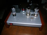
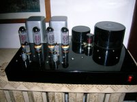
For yucks I've attached a couple pictures. The black amp is my 95% complete 8b copy. The other is one of a pair of Dynaco Mark II clones I'm working on at the moment. I say make m pretty!
Hey Paul,
You mention wanting to build an 8B replica. This is a good place to look first.
http://www.plitron.com/wp-content/uploads/702kobayashi18171.pdf
Those Plitron output transformers are EXPENSIVE. About $400 each for the outputs. I was almost finished with my 8b copy when I set it aside. I'm using a pair of Acrosound TO300's. You might find some 8b parts from the reissues built by VAC, Kevin Hayes is a nice guy. But I'm with the others. The St 70 is a much better place to start. The 8b is a really complicated amp.
For yucks I've attached a couple pictures. The black amp is my 95% complete 8b copy. The other is one of a pair of Dynaco Mark II clones I'm working on at the moment. I say make m pretty!
Attachments
- Status
- This old topic is closed. If you want to reopen this topic, contact a moderator using the "Report Post" button.
- Home
- Amplifiers
- Tubes / Valves
- KTA-HiFi ST-70 pcb or marantz 8b. HiFi build