I'm trying to bust a 60 cycle hum. A friend told me how to make a homemade AC probe that can be used with a DMM.
I have a very good DMM for voltage but I must be doing it wrong. He said to wind it like an air coil overlapping back and forth.
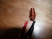
Here's my version that didn't work. Can someone tell me the proper way to make one? Much appreciated.
I have a very good DMM for voltage but I must be doing it wrong. He said to wind it like an air coil overlapping back and forth.
Here's my version that didn't work. Can someone tell me the proper way to make one? Much appreciated.
Attachments
Yes, I want to make a AC probe that will allow me to pick up stray AC fields in the power supply to try and see where the AC fields are building up and see if I can fix that and the hum. I have this one. Its their top of the line and quite good for voltages EX570 - 12 Function True RMS Industrial MultiMeter with IR Thermometer
Looks like you're building a sniffer. Those work great with spectrum analyzers, oscilloscopes and the like that have a good, low-noise, high sensitivity input amp. They work wonders for finding sources of RF oscillations and the like. A sniffer for those kinds of applications tends to be a few (often just one) windings soldered to the end of a coax cable.
But I doubt your DMM has a low enough AC voltage range to make use of it. And it won't pick up much at 60 Hz anyway -- except for transformer leakage fields and such, which you don't want.
Your best bet is to trace the grounds and signals around. Eliminate any excessive loop areas in ground/signal routing. Are you sure it's 60 Hz hum? If it's 120 Hz, it's likely to be caused by supply ripple. Try doubling the reservoir cap temporarily and see if that reduces the hum. If it's caused by supply ripple, the hum should be reduced by half.
If you actually want to measure where the hum is injected (assuming it is capacitively or inductively coupled into the circuit) your best bet is probably to get a frequency selective voltmeter. For example an HP 3581. Those can be had for $100-ish on ePay. Pay a bit more and get one that works...
~Tom
cool, pretty similar specs to most.
I think if you dont have a scope your best bet would be to design one")
Take a look at the many op-amp primers.
Op-amp-rectifier-summing amp-moing coil meter will do the trick.
I have a very similar thing that detects up to 1Thz.
I guess you are watching for 60/120Hz hum?
Cheers Matt.
I think if you dont have a scope your best bet would be to design one
Take a look at the many op-amp primers.
Op-amp-rectifier-summing amp-moing coil meter will do the trick.
I have a very similar thing that detects up to 1Thz.
I guess you are watching for 60/120Hz hum?
Cheers Matt.
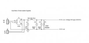
Hi Tom. Maybe it is 120 Hz I guess I would need something to measure it. It doesn't sound like a ground loop hum as I've heard those in the past. The hum does not get louder with gain. I do have more ripple than in the prototype although that was a different psu circuit. Previously I had .045vac ripple on the old supply on a bread board. The Dual mono supplies are each generating .3vac which is a big leap. I can't find what's affecting it. The circuit is super simple. Here's schematics if it helps.
Attachments
cool, pretty similar specs to most.
I think if you dont have a scope your best bet would be to design one
Take a look at the many op-amp primers.
Op-amp-rectifier-summing amp-moing coil meter will do the trick.
I have a very similar thing that detects up to 1Thz.
I guess you are watching for 60/120Hz hum?
Cheers Matt.
1THz? crumbs .... BTW I work in Tewkesbury ...
If you have a meter with a very sensitive AC volts range you could use an RF choke as a magnetic sniffer - say 10mH? This will be more sensitive than your homemade air-cored coil.
Your grounding scheme is wrong. You are injecting charging pulse noise into the PSU ground. C1 and C2 grounds should be connected together. From there a wire should connect to the secondary CT. A separate wire should go to C3 ground, then from there to the main star ground.
Your grounding scheme is wrong. You are injecting charging pulse noise into the PSU ground. C1 and C2 grounds should be connected together. From there a wire should connect to the secondary CT. A separate wire should go to C3 ground, then from there to the main star ground.
In order, I'll source an RF choke and see what happens. I did attempt that grounding scheme but didn't hear any difference. This could be due to how destructive the 60 cycle hum is. Once I can somehow figure it out I will attempt that again.
However, maybe I made a fundamental error. C2 and C3 are in parallel. The choke is going to C3 because I thought, they're in parallel so no difference. Should I break the common connection between C2 and C3 and run the choke to C2? again, since it was in parallel I thought the circuit would see one cap.
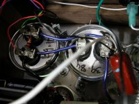
I enclosed a picture. The Choke wire is black going to C3 as are the HT leads going to the Umbilical.
DC heaters.
This from a friend overseas "a 5AR4 rectifier which outputs 5vAC on the HT rail to start with so you not only have to filter the ripple but you also need to some how filter the 5V 60Hz AC as well."
This is a dual mono preamp.
However, maybe I made a fundamental error. C2 and C3 are in parallel. The choke is going to C3 because I thought, they're in parallel so no difference. Should I break the common connection between C2 and C3 and run the choke to C2? again, since it was in parallel I thought the circuit would see one cap.
I enclosed a picture. The Choke wire is black going to C3 as are the HT leads going to the Umbilical.
DC heaters.
This from a friend overseas "a 5AR4 rectifier which outputs 5vAC on the HT rail to start with so you not only have to filter the ripple but you also need to some how filter the 5V 60Hz AC as well."
This is a dual mono preamp.
Attachments
Last edited:
Ooops, sorry I misread the circuit. Basically, from the ground of C2+C3 you need two wires: one goes back to ground C1 then on to secondary CT (this wire carries charging pulses). The second wire goes to the star point (this wire carries clean DC, plus a little harmless ripple). The aim is to keep charging pulses well away from the star point. This is basically because 'star point' is a theoretical abstraction which cannot be achieved in reality so you don't want dirty grounds contaminating clean grounds.
Ok, so I have this clear. At the moment they all go to the star which is a terminal strip with all terminals connected.
So what I tried previously was I took the lift off the terminal strip. I then had C1 and CT going there. Then a wire to essentially C2 and starred off C2 (with C3 in parallel) to the lift. I moved the heater ground (pseudo CT) to C2 and the umbilical ground going to signal box. No change.
Did I do it right?
A terminal strip with all terminals connected is not a star, it is a bus. This means that it is not even an approximation to the theoretical perfect star. One terminal, with a number of wires coming off it, is a reasonable approximation to a star.
Where? Lift or strip? The lift and the star/bus should not be anywhere near C1/CT. The scheme must be CT-C1-C2/C3-star. Then you can attach the lift, signal ground, heater CT etc. to the star.I then had C1 and CT going there
Ok. The I will change everything. I was hoping the strip with all terminals connected would be seen as a star but I understand it could be a buss.
Aside from proper grounding should this reduce my ripple as well as pulse?
Same question holds on the strip just for the C1 and CT with a wire connecting two terminals.
Aside from proper grounding should this reduce my ripple as well as pulse?
Same question holds on the strip just for the C1 and CT with a wire connecting two terminals.
The connection between CT and C1 can be as long or short as you like. If possible, it should follow the route from the secondary via the rectifiers to the + side of C1. The idea is to minimise the area of the loop carrying charging pulses. You can even wrap it loosely around these other wires.
Similarly, the ground connection from C1 to C2/3 can roughly follow the + route via the choke - again to minimise loop area. This is less of an issue here, as C1 will have already smoothed off the sharpest edges from the pulses and the choke will generate a magnetic field anyway.
I'm not sure what you are proposing for the new strips. Just remember that if you put a current down a wire then there will be a voltage drop. Wires are not zero impedance links, they are just low value resistors.
Hi Tom. Maybe it is 120 Hz I guess I would need something to measure it.
Your DMM supports it. How about using it?
Ripple will show up mainly as 120 Hz. You'll find some 60 Hz and some 180 Hz components in it (as well as higher harmonics of 60 Hz). But 120 Hz will be the dominant one usually.
60 Hz is either from capacitive or inductive coupling. One coupling path is from AC heaters.
I do have more ripple than in the prototype although that was a different psu circuit. Previously I had .045vac ripple on the old supply on a bread board. The Dual mono supplies are each generating .3vac which is a big leap. I can't find what's affecting it. The circuit is super simple. Here's schematics if it helps.
Which supply were you using for the prototype?
300 mV ripple in my DHT power amp will result in an audible hum in the speaker. I can hear it when I'm close to the speaker. I can't say how that translates to your circuit, though.
If you went from 45 mV to 300 mV ripple on the B+ between prototype and final implementation, you need to find the cause. If the schematic hasn't changed between proto and final, then I'd suspect a bad solder joint or ground loop.
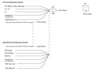
It looks like you've put some thinking into the grounding scheme... However, it also looks like you're returning signal ground and the decoupling ground for a 40 uF cap on the same ground line. That may cause trouble.
Was the prototype stereo or mono? A ground loop can be formed by the interconnect cables from the preamp to the source. Been there, debugged that.
~Tom
Last edited:
Hi Tom. You're in the other thread too. Its 60Hz. The prototype was stereo/regulated in front of what I have now. Since I didn't board this psu its hard to say if it would be the same as I'm seeing now. A friend who has an amp company said the regulated supply is what took care of most of the ripple. So I need to find a new way to lower it. I added another 180uF cap in parallel to see what effect it would have and there was zero effect.
I perfected the grounding in the prototype but I can play with it in terms of what's mentioned here once I get the main culprits resolved.
I perfected the grounding in the prototype but I can play with it in terms of what's mentioned here once I get the main culprits resolved.
- Status
- This old topic is closed. If you want to reopen this topic, contact a moderator using the "Report Post" button.
- Home
- Amplifiers
- Tubes / Valves
- How can I make a DIY AC probe for my DMM