How many volts at 180ma do you recommend?
Max 0-250vac, minimum 180ma
As for the ripple. Good idea. I remember when I used to build half wave solid state rectifiers I would use a 2200uf in paralle with the output after the rectifier diode. I don't know if that would be practical in this application as the output was always a bit higher than the pre-rectified transformer output.
Large value high voltage capacitors are very, very expensive!
I did say minus 24 volts. I am aware it is negative.
Sorry, this is more about my lack of knowledge of how this amp works...........
ps Ive seen some schemes were the -24v grid bias was derived from a heater circuit.
I believe it (I will go check the online catalogs to confirm the prices on 2200uf 450wvdc polarized electrolytics. As for the power transformer... Right now, the deal is on one that is 160ma, buy it now for $49 U.S. I will be going for that one for now. I don't know how well a toroid is going to work vs the standard transformer but the price is easier for me to come up with the needed scratch.
As for a separate bias as being a take off of the filament supply. I may even do that too. as I can get a 24v-ct transformer (500ma) that has two 12v sections. one side could be used for the 12ax7s and the two sides could provide the -24 for the grid bias.
As for a separate bias as being a take off of the filament supply. I may even do that too. as I can get a 24v-ct transformer (500ma) that has two 12v sections. one side could be used for the 12ax7s and the two sides could provide the -24 for the grid bias.
Max 0-250vac, minimum 180ma
Large value high voltage capacitors are very, very expensive!
ps Ive seen some schemes were the -24v grid bias was derived from a heater circuit.
I found several suppliers of these 2200uf caps with 450wvdc. they are very pricey! One quote was for $70 (approx)  However, there are two on ebay for $38 (used) I don't know the physical size but I have seen caps the size of a soda can in ancient linear computer power supplies. GOD Help you if that thing goes BOOM! its a hand grenade! Ahem, but would one of those really kill the ripple. Which as I remember wasn't much. Now one of the caps in the original schematic was a 25uf. I can get 22uf caps fairly easily. or should I go with something lower in number such as 20uf? it is the cap near the 22K resistor in the power supply section.
I believe it (I will go check the online catalogs to confirm the prices on 2200uf 450wvdc polarized electrolytics. As for the power transformer... Right now, the deal is on one that is 160ma, buy it now for $49 U.S. I will be going for that one for now. I don't know how well a toroid is going to work vs the standard transformer but the price is easier for me to come up with the needed scratch.
As for a separate bias as being a take off of the filament supply. I may even do that too. as I can get a 24v-ct transformer (500ma) that has two 12v sections. one side could be used for the 12ax7s and the two sides could provide the -24 for the grid bias.
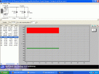
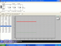
Great, now here's a scheme that brings your voltages down closer to the 230-0-230 transformer and lowers the ripple. Only a start but shows how useful it is to play about with Psud2.
The blue band across the data columns shows the voltages at C2, below shows the voltages at C3.
View attachment 213420
Interesting. Sadly, I don't have windows and I don't have this software so... Just for a lark. what would happen if I put a 2200uf cap instead of the 220uf? Seems the output with the 220uf cap still is a little wide.
Now for the help of the people who can look at this schematic and figure the wattage of these resistors on this schematic. which are 1watt, 1/2 watt, 2 watt and 10 watt? The PS ones are wirewound 10 watt ones right?
I ask as I found a svetlana 6bm8 push pull design that uses the max voltage of 300vdc at 150ma and that schematic shows some large resistors in places that I haven't thought of. I saw a picture of the original saf-24 underside and most of them were wirewound in 5 and 10 watt sizes.
I did try to write the "grocery list" of parts but I may have missed pieces. here is what I wrote (broken down by sections)
Power Supply Section: (assuming I had a 230-26.5-0-230-6.3-5 150ma transformer (remember, the original 6ca4 was indirectly heated at 6.3
Capacitors
2 40uf 450vdc polarized
2 25uf 450vdc polarized
1 50uf 450vdc polarized
Rectifiers
5u4gb
1A silicon power supply diode (for grid bias)
Resistors. Not sure of the ideal size. 10 watts?
10k
470
15k
220k
22k
amp section
12ax7 matched pair, already bought and on their way.
6bm8 matched quad. NOS Sovteks from russion. on watch list of ebay
capacitors
2 100pf 450vdc
2 0.001uf 450vdc
2 0.01uf 450vdc
2 200pf 450vdc
2 20pf 450vdc
Resistors
Not exactly sure of power rating. 1/2w 5% tolerance best guess
2 220k
2 330k
2 33meg
2 22k
2 47k
2 100k linear taper pot
2 1meg linear taper pot
1 1meg audio taper volume with loudness tap
2 10k center taped audio transformers 4/8/16ohm secondary
4 dpdt slide switches
3A Slow blow fuse
If someone can fill in the missing parts, if there is any? and the power ratings of the resistors I can revise my list.
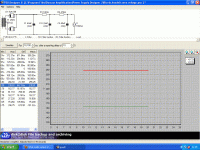
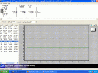
Oh baby! does that line look smooth or what? How much inrush current are we talking about? 160ma? how many ms (miliseconds) draw on the transformer and 5u4gb to charge? Lastly, and this is a safety issue. what size bleeder resistor should one use across the terminals of the caps? I can calculate the valuem I just need the equation.
Software is warning that charging this cap up is drawing a lot of initial current.
View attachment 213432
Last edited:
These are the warnings,
Warning 1 = A current sink has pulled the voltage below zero for more than 5 main cycles, at a time 0.100125s
Warning 2 = The rectifier IFRM (current forward repetitive maximum) of 1.00A has been exceeded with a value of 1.01A, at time 0.22612s
This is what the curves look like.
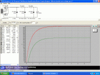
Normally a 2w 100k bleeder resistor does me but then I don't have that much capacitance
Warning 1 = A current sink has pulled the voltage below zero for more than 5 main cycles, at a time 0.100125s
Warning 2 = The rectifier IFRM (current forward repetitive maximum) of 1.00A has been exceeded with a value of 1.01A, at time 0.22612s
This is what the curves look like.

Normally a 2w 100k bleeder resistor does me but then I don't have that much capacitance
hmm. Its usable but this is only Part of the issues involved. here is the list of issues I can see
1. It gives the 5u4gb a heart attack
2. the 2200uf caps are extremely expensive
3. that much capacitance is DANGEROUS!
 Especially with 250 volts at the two lugs.
4. hook it up wrong and you got a hand grenade!
5. the capacitor physically huge!
Therefore, the choice of a 220uf cap is not the most practical, given the circuit and the space available in most designs. I do appreciate you running the numbers though. What can we do to make it as smooth as with the 2200uf with what available caps that can be readily sourced at a reasonable price?
1. It gives the 5u4gb a heart attack
2. the 2200uf caps are extremely expensive

3. that much capacitance is DANGEROUS!
4. hook it up wrong and you got a hand grenade!
5. the capacitor physically huge!
Therefore, the choice of a 220uf cap is not the most practical, given the circuit and the space available in most designs. I do appreciate you running the numbers though. What can we do to make it as smooth as with the 2200uf with what available caps that can be readily sourced at a reasonable price?
These are the warnings,
Warning 1 = A current sink has pulled the voltage below zero for more than 5 main cycles, at a time 0.100125s
Warning 2 = The rectifier IFRM (current forward repetitive maximum) of 1.00A has been exceeded with a value of 1.01A, at time 0.22612s
This is what the curves look like.
View attachment 213441
Normally a 2w 100k bleeder resistor does me but then I don't have that much capacitance
Are you up for the cost of a choke? say 5-10H.......
How much does a choke cost from Edcor or Hammond?
How much does a choke cost from Edcor or Hammond?
Note to self. as much as an audio output transformer at $38 for a 10H at 200ma. 1/2 that of a new 2200uf cap at 450v. as listed at Edcor's web site
This project is nickle and dimeing me to death!
Bichela's 6bm8 amp project.
I was tossing around some ideas to get glitzy and throw a few meters on the front. Lumi, my life partner, thought that was overdoing things. Meters to meaure input VU, B+ voltage from the two takeoffs of the power supply. Meters to measure ma from the power supply. a HV toggle that allows the tubes to stay toasty without having all that b+ floating around causing cathode damage, remember, the originally rectifier was indirectly heated. the 5u4gb is directly heated and warms up faster. a NEON NE2 glow lamp on the B+ to show when the rectifier is primed and ready. Bleeder resistors in the caps. She recommended that I build it as per the original schematic and go from there. Except Earth that chassis via the earth pin of a 3 pin mains plug.
Actually, RCA came up with that idea eons ago. Yeah, it saves parts. I like the controls and I will keep it that way. I am unsure if the controls are linear taper or audio taper though.Holy crowly. what a screwball design. Putting tone controls in the feedback loop from the OPT secondary is a really cheap and dirty way of eliminating a "proper" tone control stage. I guess that's typical Rat-Shack design.
You mean a rheostat from the C- line that feeds the two junctions of the two 470K resistors? in both the right and leff channels. How big in ohms is this recomended resistor from cathode to ground? I may consider the grid bias voltage adjust to set the voltage to the recomended -24V.If I were making this amplifier, I would add balance adjustments for the bias on the output tubes. A small pot between the two 470K grid resistors where the negative voltage comes in. I'd also add a way of measuring the tube current, like a very small resistor in each 6BM8 cathode to ground.
I was tossing around some ideas to get glitzy and throw a few meters on the front. Lumi, my life partner, thought that was overdoing things. Meters to meaure input VU, B+ voltage from the two takeoffs of the power supply. Meters to measure ma from the power supply. a HV toggle that allows the tubes to stay toasty without having all that b+ floating around causing cathode damage, remember, the originally rectifier was indirectly heated. the 5u4gb is directly heated and warms up faster. a NEON NE2 glow lamp on the B+ to show when the rectifier is primed and ready. Bleeder resistors in the caps. She recommended that I build it as per the original schematic and go from there. Except Earth that chassis via the earth pin of a 3 pin mains plug.
Last edited:
Guitar amp audio transformers but few hifi ones on egay
Just letting all of you that after several years, I am getting the parts to put this beast together around November when I get a rebate from Connecticut.
Edcor has the transformers but with shipping included the single one a 6.6k pp 4,8,16 ohm output is quite expensive. model cxpp30-ms-6.6k
I see a few guitar audio output models for less. However, I can see they are often limited to a bottom of 50 and many are limited to a top response of 12-17khz.
Here are a few examples on ebay:
OT20PP Output Transformer 25VA 8K 6K6 to 4 8 16 Ohm Imported | eBay this seller did not list frequency response. The next item, it is listed and a bit low for 20hz-20khz use. as it is 70hz to 15khz. this is the listing
Output Transformer 22W 6600 Ct Tube Valve DIY EL84 Audio Fender OT PP 6K6 Ohms | eBay
Should I consider these or stick with the Edcor?
Boost converters or traditional transformer power supply
It is the 21st century. and Switch Mode Power Supplies are all the rage. Now, I have two choices of power. The first is a
Antek 200VA 230-0-230v (200ma) 6.3V@4A round transformer.
with a small 120v to 24VAC thermostat transformer to make the bias voltage.
Not too bad in price but... you can get two of these:
DC DC Boost Converter 8 32V 12V to ±45V 390V High Voltage ZVS Capacitor Charging | eBay
which could be adjusted to give the -bias at 50v (a 330 ohm resister could bring it down to 24v to feed the original filter circuit. A second one could provide the +300 that would feed the HT circuit. Thus no rectifiers, No transformers and you can (theoretically anyway) run it off a deep cycle battery or a standard ATX power supply.
Problem is. these use a high frequency of 75khz and will need an input cap of about 2200uf to keep the +12v supply quiet as the filaments would be wired to work off that too.
Is this new tech workable for this application? I have not seen too many people using it in a tube amp.
Last edited:
I'd add one more thing to the list. A different schematic. Did that sound snarky? I hope not.
But seriously, you're going to put alot of time and plenty of money into this project. Why go with the bargain bin design?
sigh,
6MB8/6F3P/ECL82 tubes have gotten so expensive/rare that could be a deal breaker. Trying to buy 4 of them from the Winged-C Svetlana factory isn't hard but you got to ship from Ukraine to Connecticut. How many bumps can the package expect? Would they even be usable upon arrival?
Lets talk the other part of the thing. The Listener and her hearing
My hearing is not great. I have loss of the low frequencies, Midrange and high end is okay. I live in a flat that is part a 10 unit building, it was built in 1860. It has standard lime plaster walls with wooden lath. I don't need to go "Megadeath loud" That would be cause for eviction.The 12x12 room this would be used in has bare wooden floor, no rugs, a large couch and a table. it would be driving two JBL floor speakers that I bought eons ago at a tag-sale. The SPL/m is very good as it drives an older low watt 6V6 SE mono amp. On this vintage amp. the bass is very minimal. could even be due to the thing was never recapped. (another use for the parts I am buying, they can be used to fix my existing tube equipment such as the 6V6 SE and a Panasonic AA5 radio that is in my kitchen.
EL84 tube amps have a similar configuration but use a 12ax7/6n3p driver tube. it uses a more common 8K PP output transformer. I got a dynaco schematic for the EL84 that is quite easy to implement with what I have. Are the tubs less costly? Yes they are. from the same seller. I can get them for $3 less each.
Down side is you need to use a phase inverter as the EL84 does not have one built in. Whereas the ECL82 does have that feature. Thus the 6n3ps would only be in my phono RIAA preamp stage. I am using the NOS Winged-C tubes as I am buying them all from one seller. I am ordering 8 6F3Ps and 6 6N3Ps. which have a similar filament configuration to a 6AX7 with the series filament wired on pins 5 and 6 for 6.3v
I still have yet another 6BM8 schematic that is a simplified version of the SAF-24 one. it has no tone controls. and is easier to create. I could build that one too, all of these use the same basic components as I bought them in larger starter kits of all values of resistors/capacitors so I have the flexibility.
I hope to have this finished by December of 2016. As for it being bargain bin? When the amp came out around 1962 it was still an expensive amp in 1962 dollars. Even though part of mine was full of bad caps and snapped and crackled it still sounded okay, used it as a mono amp and left the left channel disconnected. If I saved it and recapped it and replaced dodgy resistors it would be almost equal, possibly better, to a Chinese EL84 PP amplifier. The turn off on the Chinese amps is the lack of tone controls and thanks to DMCA.... they don't have to give schematics either. With what I have, I got the info to tweak things as I go along. I may even modify it and calle it a MAF-24, a Mono Audio Amplifier-24 as the need for stereo isn't a big issue to me. just the two channels to one. That means only one Edcor 6.6k audio transformer. It would use less filament/plate voltage and be good enough for my needs too. Like I said, I don't have to rush into this project. It has been 5-6 years, I doubt a few more months is going to make a difference. the Audio Transformer would be the last piece as it is one of the more expensive parts.
Attached are 2 schema pulled from my collection that show the 2 topologies these tubes are usually used in. I'm partial to the LTP phase splitter. A CCS or a big B- makes the input trafo moot.
dave
In the second gif, is that a 8k-pp output transformer?
- Status
- This old topic is closed. If you want to reopen this topic, contact a moderator using the "Report Post" button.
- Home
- Amplifiers
- Tubes / Valves
- What audio output xfmr for a 6BM8 pp amp?
