ok ive put together an EL34 PP amp with a torroidal power transformer, the power supply is pretty simple, just look at any amp and itl be similar, it has a HT winding 350v RMS bias winding 35vRMS and 3 6.3 windings for heaters.
i turned it on yesterday left it in standby and the bias supply caps exploded, when i checked the voltage at the output it was -120 volts! i checked the rectified HT voltage which was at 520! i didnt check the heater windings but they were all glowing about how they should be. id tested the transformer before and everything was fine, and HT after rectification with a 120uF reservior cap and 200k load was about 485, about what id expect, (on this test there was nothing attatched to the bias or heater windings) someone said becasue of the construction of torroidal transformers its usual for the output to drift up a few volts, but surely not like this? any help is greatly appreciated! i dont really like the smell or sound of exploding caps.
i turned it on yesterday left it in standby and the bias supply caps exploded, when i checked the voltage at the output it was -120 volts! i checked the rectified HT voltage which was at 520! i didnt check the heater windings but they were all glowing about how they should be. id tested the transformer before and everything was fine, and HT after rectification with a 120uF reservior cap and 200k load was about 485, about what id expect, (on this test there was nothing attatched to the bias or heater windings) someone said becasue of the construction of torroidal transformers its usual for the output to drift up a few volts, but surely not like this? any help is greatly appreciated! i dont really like the smell or sound of exploding caps.
Hi there,
a schematic of the power supply/amp would be very helpful, especially concerning the bias supply and the way the standby switch works.
Greetings,
Andreas
Edit: Could one of the forum mods change the topic for some clarification, the toroid power transformer is not likely the problem here...?
a schematic of the power supply/amp would be very helpful, especially concerning the bias supply and the way the standby switch works.
Greetings,
Andreas
Edit: Could one of the forum mods change the topic for some clarification, the toroid power transformer is not likely the problem here...?
Last edited:
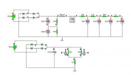
heres the power and bias supply, the CT of the output transformer is straight after the switch, then the screen grids after the 220 ohm resistor (this will eventually be replaced by a choke) then after the 2.2k resistor is the supply for the preamp. the pots go out to 220k resistors which go to the el34 control grids before the grid resistor.
Attachments
Make and model of transformer? Is it intended for 50Hz mains? Was it fairly fully loaded, or only lightly loaded?
Wild guess: the transformer was saturating and generating spikes on the 35V secondary, which led to overvoltage on the bias supply. Could be saturating because: intended for 60Hz, too lightly loaded, mains voltage too high, cheap and manufacturer sailed too close to the wind when designing it. Some cheaper transformers are near saturation even when fully loaded, and get worse at light loads.
You didn't buy it cheap off ebay?
VAL9899 : Input: 230v Output 350v 200ma 36v 50ma 2 x 0-6.3v 2amp 6.3v 3.5amp theres the transformer, pretty sure its intended for 50hz, and i know there are pretty high end products that use these transformers. the standby switch was on, all the 6.3 v windings were used, (2 EL34s on the 3.5A with a footswitch/channel switch circuit) totals at about 3.3A, 3x12ax7 on 2.2 (6x0.3=1.8A) 2x 12ax7 on 1.5a (4*0.3=1.2A)bias supply hardly draws alot, probably 10mA max
it worked fine when HT was tested with nothing loaded except for the first rectifier and filter stage.
it worked fine when HT was tested with nothing loaded except for the first rectifier and filter stage.
The output voltages of a transformer don't drift regardless of which type of transformer it is. The turns ratio sets the output voltage for a given input voltage. Naturally, any DC resistance of the windings will cause the voltage to droop when the transformer is loaded. That's also regardless of the transformer type.
The mains voltage typically varies +/-5 % (used to be +/-10 % or higher) as a function of load on the grid and other variables.
If the transformer is designed to supply 350 V and 36 V from 230 V, the output voltages could vary in the ranges of 332~368 V and 34~38 V respectively.
Without load, the reservoir caps will charge up to sqrt(2)*Vrms so the worst case output voltage should be: 368*1.414 = 520 V and 38*1.414 = 53.7 V.
So I'd use two 400 V caps for the HT and an 80 V cap for the bias supply. A 63 V could do, but I don't like to cut it too close with the voltage ratings.
Assuming the caps are rated at or beyond that, the only things I can think of that would cause them to explode would be reverse voltage or ripple current. The latter would be more of a silent killer, though. It tends to dry the caps out over time and not cause immediate destruction.
Is it possible that you forgot to tie the grounds on both circuits to the same node?
~Tom
Turns ratio only sets output voltage when the transformer is acting like a transformer i.e. not saturating.
Try running the transformer off-load, and monitor each secondary with a 'scope. You should see a sine wave or some close approximation (depending on how clean your mains is), at about the right voltage or a little high. Look for spikes. Then connect the rectifier to one secondary, and look at the other secondaries. Are there switching spikes? Spikes might not matter for a loaded sec/bridge/cap, but off-load there is nothing much to discharge the caps so they can gradually charge up to the full spike level.
Remember, there is always an explanation and we can usually find it if we don't jump too quickly to conclusions. Also remember that operator error is the most common explanation!
well the +/- 5% thing would explain 520v on the reservoir cap (2 500v 220uF in series so no problems there)
im dead certain about that 36v supply though, the caps were fine and everything was polarised right, verything was grounded, that was checked after every ground wire i put in, but there was definately around 84v RMS on that 36v winding i could try a bleeder resistor on it, ive changed the filter cap to 47uF 200v and il add a 70v (or somewhere there abouts )zener so there isnt a negative supply the EL34 grid cant handle, im sure its not saturating.
im dead certain about that 36v supply though, the caps were fine and everything was polarised right, verything was grounded, that was checked after every ground wire i put in, but there was definately around 84v RMS on that 36v winding i could try a bleeder resistor on it, ive changed the filter cap to 47uF 200v and il add a 70v (or somewhere there abouts )zener so there isnt a negative supply the EL34 grid cant handle, im sure its not saturating.
- Status
- This old topic is closed. If you want to reopen this topic, contact a moderator using the "Report Post" button.
- Home
- Amplifiers
- Tubes / Valves
- torroidal power transformers