Folks,
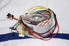
As the Antek AS-xxx models aren't spec'ed on Antek's site, I figure I'd share some measurements performed on the AS-4T430 transformer. The AS-xxx models are the shielded versions of the AT-xxx and according to John Ango of Antek Inc, they should be identical except for an electrostatic shield between primary and secondary and a 'belly band' around the outside of the core.
I have to say that the Antek transformers were never pieces of industrial art and the 'belly band' certainly doesn't improve the looks. But conveniently, Antek sells some bells that mount over the transformers which make them aesthetically acceptable to mount topside on an amp chassis.
PRIMARY:
2 x 115 V
DCR: 2.64 ohm each winding
SECONDARY:
2 x 430 V with a tap at 70 V
DCR: 32 ohm each 430 V winding
2 x 6.3 V, 4 A
Measurements @ 300 W load:
110 V AC IN; 391 V AC OUT; 743 mA sec. load current
114 V AC IN; 402 V AC OUT; 760 mA sec. load current
115 V AC IN; 408 V AC OUT; 760 mA sec. load current
120 V AC IN; 426 V AC OUT; 778 mA sec. load current
126 V AC IN; 447 V AC OUT; 799 mA sec. load current
Measurements @ 80 W load:
110 V AC IN; 406 V AC OUT; 191 mA sec. load current
114 V AC IN; 421 V AC OUT; 194 mA sec. load current
115 V AC IN; 426 V AC OUT; 196 mA sec. load current
120 V AC IN; 444 V AC OUT; 200 mA sec. load current
126 V AC IN; 467 V AC OUT; 205 mA sec. load current
The measurements for 300 W load were performed by using four 100 W, 120 V light bulbs in series for the secondary load. For the 80 W load condition, four 25 W bulbs were used. In both cases, the two secondary windings were in parallel. The two primary windings were in parallel as well. The primary voltage was adjusted by a variac and measured with a voltmeter. The secondary voltages and currents are measured values.
~Tom
Attachments
Data for the 70 V winding
Folks,
Just a quick follow-up. I measured the voltage of the 70 V tap on the secondary winding with the secondary loaded as for the 80 W case above. Here's the data:
110 V AC IN; 59.5 V AC OUT
114 V AC IN; 61.8 V AC OUT
115 V AC IN; 62.3 V AC OUT
120 V AC IN; 65.2 V AC OUT
126 V AC IN; 68.4 V AC OUT
So the "70 V" quoted by Antek is more like 60 V. Still... Quite useful for a bias tap.
For this measurement, the 70 V tap was not loaded. The entire secondary winding was loaded as post #1, 80 W case.
~Tom
Sorry guys. I measured the wrong winding and was actually measuring some random coupling. My bad. Here are the correct figures for the 70 V winding:
110 V AC IN; 68.8 V AC OUT
114 V AC IN; 66.3 V AC OUT
115 V AC IN; 69.4 V AC OUT
120 V AC IN; 72.6 V AC OUT
126 V AC IN; 76.1 V AC OUT
The two secondaries in parallel, loaded by 4x25 W light bulbs (about 80 W actual load). Measuring the voltage on the 70 V tap.
~Tom
110 V AC IN; 68.8 V AC OUT
114 V AC IN; 66.3 V AC OUT
115 V AC IN; 69.4 V AC OUT
120 V AC IN; 72.6 V AC OUT
126 V AC IN; 76.1 V AC OUT
The two secondaries in parallel, loaded by 4x25 W light bulbs (about 80 W actual load). Measuring the voltage on the 70 V tap.
~Tom
Russ - good catch.
It's two windings 0-70-430. The windings are identical and not symmetrical. So when wired in series, you'd get 430-360-0-70-430.
I suspect that if one keeps the load on the 70 V tap light relative to the total secondary load, it would probably be OK. I'll be using it with a voltage doubler to run the input stage of my amp (needs about 160 V).
~Tom
OK, well at least they are consistent. ")
With respect tot he red board, using a single 70V for the bias supply is fine. The current demand is low and Pete even confirmed he had been using a Hammond with a single bias tap prior to having the custom Edcor.
A more interesting question is this: could the PCB drive the input/driver tubes and output tube screens with only a half wave rectifier? In other words, if one were to use the 430-0-430 on a separate CLC filter and connect those to the output tube plates (similar to what George did with his dual-10-pounder setup), could one use the ripple filter to clean-up the single 360V tap and power the PCB with that? How about if the board is modded to run the screen regulator from the 430-0-430 supply and only run the input/driver tubes from the 360V tap?
I wouldn't know about the Red Board. I'm using the transformer in a directly coupled 300B SET design. My requirements are (per channel):
+470 V @ 100 mA
-160 V @ 10 mA
Possibly +160 V @ 5 mA.
All supplies except the +160 V will be regulated. +/-160 V are derived by voltage doublers from the 70 V tap.
At worst case V(AC)in, I should have about 25 V headroom across the regulator for the 470 V. Cutting it close, but it should be alright.
~Tom
- Status
- This old topic is closed. If you want to reopen this topic, contact a moderator using the "Report Post" button.
- Home
- Amplifiers
- Tubes / Valves
- Antek AS-4T430 measurements