While waiting on my edcor transformers, I have started designing my next project. I'm hoping someone more experienced can take a peak at this and make sure that I'm not doing anything too stupid.
The main requirement for this SE direct coupled monoblock tube amp is that it must be small and portable, while still sound good. I therefore used the combo tube 6ea7/6em7 and I am dispensing with a choke in favor of a RC ladder filter like in Morgan Jones' book. When looking at the datasheet for the 6ea7, the recommended operating points are a bit different than with a normal two stage amp. The recommended operating point calls for the driver stage sit at a higher (250V) B+ than the power stage (150V). After looking at power supply designs and grounding schemes that would accommodate this, I floundered upon direct coupled designs, which would solve and simplify the power supply design.
I know these direct coupled designs tend to blow up when things go wrong, and the monkey design fixes it and reduces wasted power, but more components will add size, which I do not want. Also these tubes are relatively cheap and I'll be using properly rated components and fuses, so I'm not too worried about a failure.
Many of the designs I see call for loading the driver anode with a choke. I don't quite understand the need for this and would appreciate an explanation. Since I'm dispensing with a choke in the power supply, one here would not do.
The anode of T1 sits at 250V, idles at 180V, biased at -2V and takes 1.8 ma at idle. The operating point of T2 is at 150V at 50ma, biased at -20V. So, the cathode of T2 needs to sit at 180+20=200V and the anode needs a B+ of 180+150+20=200+150=350V. The cathode resistor needs to drop 200V at 50ma, so 3.2kOhms. Make sense?
Thanks all.
Attachments
I know these direct coupled designs tend to blow up when things go wrong, and the monkey design fixes it and reduces wasted power, but more components will add size, which I do not want.
All you'd really need is an extra coupling cap and bias resistor, which really won't add much if any extra size to the amp. You already have the OPT, power transformer, filter cap and tube, which are the bulky items anyway. And I hate to think of the power you're gonna burn in that cathode resistor. Which means a bulky power resistor probably bigger than the coupling cap and bias resistor anyway. Avoiding that power resistor would allow a smaller power transformer anyway.
The small triode’s plate resistance according to the data sheet is 30K. Your plate load, R1, is only 39K, which is way too small if you want full frequency response. A choke offers many advantages that you can find searching here.
The high plate resistance of the small triode of the 6EA7 and your small package size requirement may be better served by a constant current source, which can provide high impedance with little loss in voltage, around 30Vs or so.
If that is all the mains voltage you have to work with, you may be hard pressed to monkey with a constant current source, though a high-henry choke works. It’s a nice tube and worth playing around with.
Matt
As you noted, the 6EA7 has characteristics very similar to the 6EM7. If someone can tell me precisely where they differ, it would be appreciated. A well tested and proven direct coupled design for the 6EM7 can be found here:
6EM7 DC Coupled Triode Tube Amplifier
I'd suggest you start with that. Don't neglect the high wattage rating of the cathode resistors.
6EM7 DC Coupled Triode Tube Amplifier
I'd suggest you start with that. Don't neglect the high wattage rating of the cathode resistors.
Last edited:
I can't find the graphs for the 6ea7 like I can for the 6em7, so I haven't found out how they differ yet.
I've seen that battery biased design. Somehow I missed it when I was designing mine, but when I did find it I was reassured. Is there a burning reason he decided to use a battery bias?
With my operating points, I'd be burning 10 Watts in the cathode resistor. That kind of dissipation may need a heat sink. I have found that I don't quite fully understand Monkey amps enough yet to go that route. Maybe further down the line. I guess I'll put two or more cathode resistors in parrallel if I want to avoid a heat sink.
mwiebe, I printed out the graph for the 6em7 and drew the load line I wanted and then calculated the plate load resistor. Can you elaborate on the relationship between the tube plate resistance and the plate load resistor? I know that it is generally a tradeoff between linearity and voltage swing. The more plate load you have, the more voltage swing you can get. The less resistance, the more linear.
Many of the designs I see call for loading the driver anode with a choke. I don't quite understand the need for this and would appreciate an explanation.
It seems to be explained here:
"Usually you would want some margin of voltage to allow the driver to swing more voltage than the output tube would require to drive it to full output, but in this design it is not possible. This led me to believe that a choke was the only appropriate plate load for the driver tube."
- Boozhound Laboratories
Radio Designer's Handbook, Morgan Jones, and others go into triode loads. Three times plate resistance is a decent starting point. A constant current source, CCS, is many times higher and can diminish some distortion.
If you just want to build an amp, the Gary Kaufman’s design, linked above, has been built by many and sounds great. If you want to puzzle out your own amp have at it that’s what this is about. Sometimes it’s easier to solder and listen and then figure out what to do to change what you hear.
Matt
If you just want to build an amp, the Gary Kaufman’s design, linked above, has been built by many and sounds great. If you want to puzzle out your own amp have at it that’s what this is about. Sometimes it’s easier to solder and listen and then figure out what to do to change what you hear.
Matt
With my operating points, I'd be burning 10 Watts in the cathode resistor. That kind of dissipation may need a heat sink. I have found that I don't quite fully understand Monkey amps enough yet to go that route. Maybe further down the line. I guess I'll put two or more cathode resistors in parrallel if I want to avoid a heat sink.
There is no need to guess here, you *will* need a heat sink at those power levels.
")
Attempting to spread out the heat a bit by using two resistors in parallel will not get you anywhere. Ultimately all the heat generated inside/below your chassis has to get out into the free air. So for a given amount of power dissipated as heat, the temperature increase of your chassis will *only* depend on how well it acts as a heat sink. This is regardless of how many components are used to generate the heat. Components heats air below chassis, air heats chassis, chassis act as heat sink, increasing its temperature until equilibrium is reached. Simple.
And ventilation holes will only help in a minor way here, unless you use really big ones. Hot air moves quite slowly through small holes, unless forced by a fan.
So try putting a hot 20W soldering iron inside a scrap chassis about the same size as your planned amp. [1] Use a flame proof surface, please. Close holes with more scrap metal as required, and leave the soldering iron there for a few hours. Then check chassis temperature, and you will have an idea of how hot the chassis will get at 20W dissipation. My suspicion is that it will be hot...
And the components inside a real amp would be way hotter still. They have to increase their temperature up to a point, where they can heat the chassis enough to allow it to work as the global heat sink.

You could also try to calculate how large a heat sink you would need, if, say, you wanted a temperature increase of 20 degrees C (35 F). That is a reasonable figure used if you want long lifetime of components, like electrolytic capacitors. Note again this is the temperature of the *chassis*, not the components and the air inside. They will again be hotter than this, which is why you want to limit yourself here.
20W/20 deg C means a heat sink of thermal resistance of 1 K/W. I happen to have one on my desk with double that value (when corrected for only a 20K temperature rise). It has 11 fat fins, and is 100mm (4") wide, 75mm (3") high and the depth (thickness of base plus height of fins) is 40mm (1.5"). One of these, when placed with fins vertically and in free air, including below (impressive how many forget this...), will dissipate 10W at a temperature increase of 20 degrees C. So you will need two of those. Or have to accept a proportionally higher increase in chassis temperature.
[1) Actually, don't. This is likely to ruin the soldering iron.
Wow, that is a lot of heat. Thanks for the great description. I guess I'll find a way to fit a heat sink in, or take the time to really learn the monkey design. As a last result, I can use a coupling cap and scrap the direct coupling, but I really wanted to do something different.
Wait a minute. Looking at a couple monkey amps, the cathode resistor still has to drop all that voltage. I thought they were a solution to the heat problem, but I think it only solves the blowing up problem. Do ALL direct coupled circuits have this problem?
Wait a minute. Looking at a couple monkey amps, the cathode resistor still has to drop all that voltage. I thought they were a solution to the heat problem, but I think it only solves the blowing up problem. Do ALL direct coupled circuits have this problem?
Last edited:
Well, you need some way to keep the cathode of the output tube somewhere near the voltage of the anode of the driver tube. Usually, that means dropping voltage between the cathode of the power tube and ground using some sort of load, and given the cathode current, that means a dissipation of Vcathode * Icathode.
In your case, I'd reconsider the direct coupled topology and meditate a bit on a more regular SE concept.
In your case, I'd reconsider the direct coupled topology and meditate a bit on a more regular SE concept.
Q - why is the cathode of the final elevated so high?
A - to allow for direct coupling from the first stage while running the first stage into a 0 volt bottom rail.
Q - how could you reduce the amount of elevation required by the finals and hence reduce the heat problem?
A - run the first stage into a -ve bottom rail...
Much easier to disipate 1.8ma of heat generation than 50ma
Aha, that's why I see negative rails on some designs. Thanks to all for the advice. I'll re-read the part on anode loads from Morgan Jones and use a better load value. I think I'll stick with the direct coupled. While adding a giant power resistor of some kind does not fit my design goals, I really do want to try something that I haven't done. I think I'll go 3D and mount the power resistor on the side. Thanks again.
In that case I'd suggest using something like one of the Aluminum clad Welwyn power resistors. One of the 50W resistors will just barely dissipate 10W without a heatsink at 25 deg C, so a pair will do the job. They will become quite hot though. I would consider mounting them vertically on the rear (they are 72mm / 3" high) to increase cooling as much as possible.[...]I think I'll go 3D and mount the power resistor on the side. Thanks again.
Put the resistors on metal stand-off's/spacers of some kind to prevent heating of the main chassis as much as possible, and use Teflon insulated wiring. Most anything else will have the insulation destroyed by the high temperatures generated by the resistors. Then add a wire cage around them to deal with the electric shock hazard (one end of each resistor is at 200V).
Good luck.
sounds like a lot of trouble to avoid putting in a negative 130v rail....
I agree, but that doesn't mean I will not help doing it properly, if he wish to try this design with power resistors. It may actually save on weight/size compared to using large heat sinks or additional PSU components for a negative rail.
Just realized the original schematic contains a showstopper error. The 6EA7 is only allowed to run the heater minus 100V negative with respect to the cathode. This is for the DC components of the voltage difference. With 200V applied continuously, I'd expect the tube to be fairly short lived, until it develops a heater/cathode short and stops working. Even using a negative supply rail won't fix this, as we cannot separate the two tube heaters.
So the design either needs to use a different pair of tubes, driver and output each on their own heater supply, or the output stage should be run at a more reasonable cathode voltage via DC blocking capacitor and grid leak resistor.
Edit: Well, one could run the heater at around 100V potential, making each half of the tube run right on the edge of permissible voltage difference. A bit too close for my taste though.
Last edited:
can't see your schematics, but
it more or less makes sense.
cathode of T2 sits at 182 (T1 anode + bias) + 20 = 202V.
B+ of 202 + 150 = 352V, but you need to consider voltage drop due to output transformer primary.
cathode resistor of T2 should be around 4040R with 50mA at 10W, but you need to de-rate! factor in 3 x wattage for sustained use.
i recently completed a direct coupled 6N6P driving 1626. the 6N6P is loaded with a CCS set at around 25mA, the 1626 draws 26mA. i used a caddock MP820 5k resistor for the cathode of 1626. this is mounted onto my 4mm aluminium chassis and is just slightly warm to touch. of course, i'm not dissipating as much heat as your design.
i have a voltage divider to lift the 1626 heaters by 72v to keep it within the +/-100v heater to cathode limit of the 1626.
information on my build can be found here.
The anode of T1 sits at 250V, idles at 180V, biased at -2V and takes 1.8 ma at idle. The operating point of T2 is at 150V at 50ma, biased at -20V. So, the cathode of T2 needs to sit at 180+20=200V and the anode needs a B+ of 180+150+20=200+150=350V. The cathode resistor needs to drop 200V at 50ma, so 3.2kOhms. Make sense?
it more or less makes sense.
cathode of T2 sits at 182 (T1 anode + bias) + 20 = 202V.
B+ of 202 + 150 = 352V, but you need to consider voltage drop due to output transformer primary.
cathode resistor of T2 should be around 4040R with 50mA at 10W, but you need to de-rate! factor in 3 x wattage for sustained use.
i recently completed a direct coupled 6N6P driving 1626. the 6N6P is loaded with a CCS set at around 25mA, the 1626 draws 26mA. i used a caddock MP820 5k resistor for the cathode of 1626. this is mounted onto my 4mm aluminium chassis and is just slightly warm to touch. of course, i'm not dissipating as much heat as your design.
i have a voltage divider to lift the 1626 heaters by 72v to keep it within the +/-100v heater to cathode limit of the 1626.
information on my build can be found here.
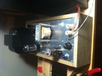
Ahaha it lives! It sounds great! And it's hot! And zero hum; none!
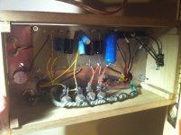
The final design changed a bit as I fell into a hammond 275X transformer and some power resistors. I am using four ohmite 25 watt adjustable power resistors. Two for the power supply and two for the power stage cathode bias. They are vertically mounted inside the chassis with a large bolt running through their middle. The bolts holding them act as a heat sink. You can put your hand on the bolt heads, but you wouldn't want to keep it there for too long. Input is from an ipod line out with a stereo to mono bridge.
The chassis is poplar, but it not finished yet. It still needs to be sanded and oil rubbed. The top is aluminum plate that I thought was really thick, but that giant transformer causes it to bend a little in the middle. I may have to add some more bracing.
Thanks to Knarf for pointing out the heater voltage problem. I overlooked that. I set it at half the bias voltage, which should be around 100V. I read that you said the max voltage difference is 100V, but the datasheet says 200V. I listened to it for about an hour tonight and everything seems ok. Tomorrow I will double check all the voltages and operating points and make sure everything is as I designed it.
mwjebe, I changed the driver plate load to 100K on your advice. I also looked through all the books and the web and still cannot find where the "three times" rule of thumb comes from. Can anyone point me to a reference that derives this rule of thumb? Because of the higher plate load, I upped the supply voltage to 300V to get a little better linearity, but it still idles around the same 175V with a -2V bias.
I didn't have a capacitor as big as I'd like for the power stage cathode bypass that can take the voltage. I'm only running 2 22uF 350V caps in parallel. I have by no means finished the listening test of this amp, but initial impressions may point to a small lack of bass. It's possible it is from the bypass cap, but I suspect the more likely candidate is the Hammond 125CSE OT. The frequency rolloff math works out with the 44uF cap.
My first build was supposed to be a straightforward 6sn7 6v6 build, but the pieces for this one fell into place first and I couldn't be happier. It is quite distinct from any other amp I've owned. Very warm. My computer setup sounds so harsh by comparison.
And I just got an email saying my Edcor transformers have shipped! I'm lovin this.
Btw, Tubedepot rocks. Their shipping times are unreal.
Attachments
- Status
- This old topic is closed. If you want to reopen this topic, contact a moderator using the "Report Post" button.
- Home
- Amplifiers
- Tubes / Valves
- small, light dc coupled 6ea7 amp sanity check