What about this electronic choke for valve:
SELF DE FILTRAGE ELECTRONIQUE A MONTEE PROGRESSIVE - eBay.ch (endet 19.03.11 17:38:18 MEZ)
Cost only 25€00 + shipping")
SELF DE FILTRAGE ELECTRONIQUE A MONTEE PROGRESSIVE - eBay.ch (endet 19.03.11 17:38:18 MEZ)
Cost only 25€00 + shipping
Looks like a regular pass regulator. Can be built for less than half the cost if you do it yourself; there's lots of schematics out there. If you're looking for an easy solution and don't want to get your hands dirty, this seems like a good solution. It'll dissipate a bit more power than a choke though.
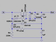
Looking at the image of the device, I think it's a transistor based voltage regulator.
Example Transistor Circuits
Constant voltage output with very good ripple rejection (as long as the input caps are large enough and the output voltage is below the ripple voltage). Simple enough to P2P or even make on stripboard. Cost of parts not more than 5 Euros. Have made many of these and use them in my circuits. Make sure the transistor can take the voltages used. I use the IRF740 or IRF840 for high voltage applications.
(edit: Looks like Mastodon beat me to it)
electronic choke
if working like a choke, it should only smooth ripple, and not be a voltage regulator, yes ?
some around here are playing with a JLH ripple killer
but probably low voltage
seems it has a voltage drop of 15V, but no voltage regulation as such
and also a softstart function
if working like a choke, it should only smooth ripple, and not be a voltage regulator, yes ?
some around here are playing with a JLH ripple killer
but probably low voltage
seems it has a voltage drop of 15V, but no voltage regulation as such
and also a softstart function
electronic choke
if working like a choke, it should only kill ripple, and not regulate voltage, yes ?
Yes don't regulate only drops max. 15V Vin-Vout
As far as I can see, if this circuit does not offer any voltage regulation, then this seems to be an even simpler circuit than the voltage regulator, the zener being replaced by another resistor. This then works as a voltage divider, probably calculated to drop a certain percentage of volts from the gate/base of the pass transistor. The voltage drop is probably enough to "chop" off the ripple voltage of about 8-10 volts.
I have also made this circuit too. Works very well.
As mastodon puts it, if you wish to have an easy life, then just buy it. It works. No doubt about it.
I have also made this circuit too. Works very well.
As mastodon puts it, if you wish to have an easy life, then just buy it. It works. No doubt about it.
Last edited:
Basically based on this,
http://www.satcure-focus.com/tutor/images/regulat.gif
replace the ZD1 with R2. Voltage drop can be calculated by Vin(R1/R1+R2). Calculate for a drop of 12-20V if you are using 400V. A good initial value to try would be R1=30K, R2=680k. You can also place a large value capacitor in parallel with R2 to improve ripple rejection, and also for slow start.
Q1 you can use irf840. All the precautions of using a Mosfet apply, ie reverse biased zener between G-S, reverse biased diode at S-D.
Alternatively, you can use this circuit concept of a capacitance multiplier.
Capacitance multiplier - Wikipedia, the free encyclopedia
Capacitance Multiplier Power Supply Filter

Wikipedia is a good source of rumor and opinions, but a bad source of reliable information. What is called a capacitance multiplier, does not work as a multiplier: it does not have a capacitive output, strictly speaking. And it does not have properties of inductance, so it is not a choke. It is a R-C filter with a source follower. A good way to filter rectified power, even to bring up output voltage slowly, using relatively small capacitance and big resistance in R-C network for a large time constant.
I saw attempts to use gyrators there, to simulate a choke. It is even worse! P-network tuned on fundamental frequency of rectified power has higher dynamic output resistance than this simple source follower with R-C network in it's gate.
Here is a more value for money version
Elektronische Drossel, Mosfet Gyrator SS Choke 200mA - eBay, Röhrenverstärker, High-End Audiogeräte, Audio Hi-Fi. (Eindtijd 24-feb-11 18:01:40 CET)
Although shipping costs are quite high.
Elektronische Drossel, Mosfet Gyrator SS Choke 200mA - eBay, Röhrenverstärker, High-End Audiogeräte, Audio Hi-Fi. (Eindtijd 24-feb-11 18:01:40 CET)
Although shipping costs are quite high.
Last edited:
A choke is heavier and more expensive. But I'm told has the ability to store energy and release it when needed.Every time I'm more confused, surely will be more easy to use an inductive choke.
But an electronic choke can simulate a choke of 90H and can then pass more current than almost all 90H chokes.
Or maybe just get the PCB:
http://cgi.ebay.nl/Elektronik-Dross...ltDomain_77&hash=item19c306ef34#ht_2757wt_962
Or this one. This one looks real nice.
http://cgi.ebay.nl/Elektronische-Dr...tDomain_77&hash=item19bafe8f5b#ht_2578wt_1185
http://cgi.ebay.nl/Elektronik-Dross...ltDomain_77&hash=item19c306ef34#ht_2757wt_962
Or this one. This one looks real nice.
http://cgi.ebay.nl/Elektronische-Dr...tDomain_77&hash=item19bafe8f5b#ht_2578wt_1185
Here is a more value for money version
Elektronische Drossel, Mosfet Gyrator SS Choke 200mA - eBay, Röhrenverstärker, High-End Audiogeräte, Audio Hi-Fi. (Eindtijd 24-feb-11 18:01:40 CET)
Although shipping costs are quite high.
Wow Bass, with this price I will buy severals.
- Status
- This old topic is closed. If you want to reopen this topic, contact a moderator using the "Report Post" button.
- Home
- Amplifiers
- Tubes / Valves
- Electronic choke