Folks,
I've noticed that on many older/classic SET designs, there are spark gaps across the OPT primary. I suppose this is to protect the OPT in the event that the amp is ever operated without a load.
I realize that one way of accomplishing the same protection is to have a very light load (say 100 ohm or 1 kOhm) on the secondary across the speaker terminals. But first off I think that's a waste of power, secondly, I really kinda like the idea of a spark gap. It's not participating in the circuit until absolutely needed.
Has anybody experimented with the spark gaps? Is there a good source for those? Or how about using one of the more modern Tranzorb surge suppression devices?
Also... To get a few more data points for the discussion here. For those who use a resistor on the secondary to protect the OPT, which resistance do you typically use? A 1 kOhm resistor wouldn't burn very much power at all, but would it offer adequate protection? I'm thinking it would, but it would be nice with some more analysis here.
~Tom
Last edited:
Even 100 Ohms on the output would not be heavy enough to stop much of a flyback effect from the output tube suddenly losing bias. (going into cutoff) A spark gap would probably do a much better job of staying out of the sonic picture until breakdown over some other kind of transient absorber.
Last edited:
Tom, only loaded secondary I have seen is the Selmer 50W PAs from the 1960s. These had 470 ohm at something like 10W on the 8 ohm tap.
The spark gaps are fun, but I believe they are slow enough to risk a "breakdown race" with the OT.
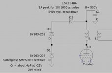
Meanwhile, the transorbs have 100 or more pF of capacitance, and it might be better to buffer that with some low-capacitance reverse-biased EHT diodes. And, the Tranzorbs stick ON when struck, so referring them to B+ might avoid needless fuse blowing....
The Sowter SA08S OTs I use are tested at 2.5kV. Here is the starting point for a protection circuit for these, if needed.
The spark gaps are fun, but I believe they are slow enough to risk a "breakdown race" with the OT.
Meanwhile, the transorbs have 100 or more pF of capacitance, and it might be better to buffer that with some low-capacitance reverse-biased EHT diodes. And, the Tranzorbs stick ON when struck, so referring them to B+ might avoid needless fuse blowing....
The Sowter SA08S OTs I use are tested at 2.5kV. Here is the starting point for a protection circuit for these, if needed.
Attachments
I use small 7mm MOVs with a series dampening resistor (similar resistance to OT primary) between B+ and anodes on PP amps - so similar should be fine here. The small MOVs with high DC voltage ratings (sometimes two in series are necessary) have less than 100pf, and the series R turns them in to a crude zobel dampener. I haven't tried them in anger in an experiment yet, but highly recommended.
Ciao, Tim
Ciao, Tim
If I were going to go with this sort of a thing, I would use back-to-back 1.5KE series transient suppressor diodes, as well as a little bit of load on the output. I feel safer with the transient suppressor diodes that clamp to a constant voltage rather than spark gaps or gas tubes that can fire at a high voltage, then collapse to a low voltage (arc discharges do that, especially with DC behind them) and blow out the power supply and/or the output transformer. Back-to back transient suppressors with a series resistor, in conjunction with a paralleled MOV or two across the lot may be an option to protect against serious abuse. A small bit of load on the output is an option to keep all the power from being dumped into the protection network. What you're really trying to guard against is having no path for the charged-up primary and leakage inductance to discharge besides the transformer insulation and the tubes and sockets. A preload can take care of a fair amount of the energy stored in the primary inductance, while the protection network will get the leakage energy that cannot be transferred to the secondary. Blowing some power in a resistor to me is a far more acceptable alternative to replacing fried output transformers, tubes, and tube sockets - what a PITA...
Imho, the first thing is to differentiate the problem areas and understand what can happen and what solutions are appropriate - rather than smear the various problems and solutions.
Of itself, driving no load with moderate signal may not stress anything if the primary is still attached to some form of 'circuit'. For example, there is still capacitance loading to secondary, which will be coupled to primary side by grounded speaker connection.
I'm newb with SET, but with PP the circumstantial evidence for OT failure is primary side insulation breakdown from either gross overdrive with no load, or a failed part that causes an effective step load change when substantial current is flowing in the OT (this also covers the 'I tripped over the speaker cable and the plug pulled out of the amp socket').
For a no load situation, the change in primary current is not huge, and the energy to capture (to constrain any primary overvoltage) is not huge. For a step load change during large primary current swing, then the energy to capture is relatively large.
MOVs or TVS across the primary, at a somewhat higher voltage rating than the peak signal level, have the advantage that they are pretty much 'inert' untill they start conducting. MOV's are typically cheaper, more available, and have higher absorption energy than TVS, and are just as fast. The operating voltage window of the protection device isn't really imho a big issue, as long as it is under the nominal insulation withstand level (eg. 1kVDC for the want of no better target).
A damped response to the protection imho has advantages to managing the problem energy, compared to a hard clamp option, but again only if it still limits to within the insulation withstand level.
For a no load scenario, the protection solution has to suit 'long-term exposure', as it may be some time before someone realises the amp is not loaded. For the more onerous failed part scenario, the protection solution really just has to act once - as long as it is appreciated that it needs replacement, along with the failed device.
Ciao, Tim
I'm having the same problem at this very moment. I'm building a tube amp which will drive an electrostatic panel through a 1:3.5 step-up transformer. You can think of it as a 1nF almost entirely capacitive load. I'm wondering if I need to add some resistive loading to the secondary.
Any ideas???
Kenneth
Any ideas???
Kenneth
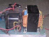
In my power (2 kW) amplifier for PA purposes I use spark gaps for protection of the output transformers because I can not see if my load is always there.
Sometimes there is about 1000 meters of speaker cables connected over the streets, and I cannot look 24/7 if something is wrong with the load.
See picture
Sometimes there is about 1000 meters of speaker cables connected over the streets, and I cannot look 24/7 if something is wrong with the load.
See picture
Attachments
- Status
- This old topic is closed. If you want to reopen this topic, contact a moderator using the "Report Post" button.
- Home
- Amplifiers
- Tubes / Valves
- Spark gaps on output transformers