I'm trying to make a Williamson amp with 6l6GC tubes in the output stage. I'm trying to calculate the resistor values but I'm having trouble with the calculations. How can I go about analyzing the original amplifier so I can appropriately choose my resistors. I have this website to see the original design and I have the 6L6 datasheet. I plan to run in push-pull AB1 for 25 watts of output power.
http://www.clarisonus.com/Archives/Amp_Design/Williamson 1952 The Williamson Amplifier.pdf
http://www.clarisonus.com/Archives/Amp_Design/Williamson 1952 The Williamson Amplifier.pdf
First, read Morgan Jones's comprehensive analysis in "Valve Amplifiers." After that, you'll know what to do to fix the major problem- LF stability. This should also get you up to speed on setting output stage conditions.
Second, read the 6L6GC datasheet carefully. Also see the variants, 7027A and 5881, which show some alternative operating conditions. You can decide for yourself the tradeoff between load, power, and distortion, as well as output stage topology (triode, UL, pentode).
Second, read the 6L6GC datasheet carefully. Also see the variants, 7027A and 5881, which show some alternative operating conditions. You can decide for yourself the tradeoff between load, power, and distortion, as well as output stage topology (triode, UL, pentode).
First, read Morgan Jones's comprehensive analysis in "Valve Amplifiers." After that, you'll know what to do to fix the major problem- LF stability. This should also get you up to speed on setting output stage conditions.
I have read Morgan Jones's book and he doesn't talk about how the stages affect each other. I am set on my choice of output tube. I need to calculate the resistor values needed throughout the driver and output stages to drive the 6l6 tubes as the datasheet says to.
Well, really, except for fixing the LF stability problem and biasing the output stage, all the values in the original KT66 version are fine. You will certainly have to alter the compensation (that has more to do with output transformer than output tubes), but that's best done experimentally.
To clarify my remark above (just in case you misinterpreted it), I was not suggesting the use of different output tubes- my suggestion was directed toward datasheets. The 7027, 7581, and 5881 are all basically 6L6 with altered pinout and bulb, so operating data for one is transportable to any of the others, within rating limits.
To clarify my remark above (just in case you misinterpreted it), I was not suggesting the use of different output tubes- my suggestion was directed toward datasheets. The 7027, 7581, and 5881 are all basically 6L6 with altered pinout and bulb, so operating data for one is transportable to any of the others, within rating limits.
Grungeman,
There are plenty of other "Williamson" schematics out there other than the one you show in your OP.
Just do a google search, The "Williamson" amp is more about overall topology, ie; Split load inverter with drivers, rather than the individual tubes or operating points.
I think that SY was actually giving you some of the best advice out there. You need to decide exactly what you are intending to get out of this. 6L6's are good tubes and SY was not questioning your choice, he simply was showing you that there are various operating conditions to run them at.
Since you want to run AB1 @ about 25 Watts I am not sure that is possible with a "triode strapped" 6L6 without significant distortion.
Give us some details of your intention and what "iron" you have available?
I'm trying to make a Williamson amp with 6l6GC tubes in the output stage.
How precisely you want to follow the original Williamson design ?
Triode or UL-ciruit for example ?
I think a 25 W 6L6 pp-amplifier can be essentially simpler than Williamson design.
There is no need to use any driver stage after the phase splitter.
Basically a voltage amplifying stage followed by long tailed pair phase splitter is just what you need to drive the 6L6 pair.
I agree with Artosalo - what he proposes will not have the well known problems with LF stability of the Williamson. Look at something like the Mullard 5-20 design topology with appropriate tube choices as an example.. 25W is achievable in AB1 in UL mode, perhaps 12W or so in triode.
I'm trying to make a Williamson amp with 6l6GC tubes in the output stage. I'm trying to calculate the resistor values but I'm having trouble with the calculations. How can I go about analyzing the original amplifier so I can appropriately choose my resistors. I have this website to see the original design and I have the 6L6 datasheet. I plan to run in push-pull AB1 for 25 watts of output power.
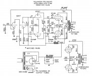
On page 34 of the collected reprinted articles, Williamson discusses the changes required if 6L6 valves are used in place of KT66. All that is recommended is to set the output stage current to 110mA total instead of 125mA total. The output stage static current is set using variable resistance R21.
A consequence of this is that you will have to give up a couple of watts of output power.
I would certainly not discourage you from building a Williamson amplifier. To say that it is a classic design is a great understatement – after this design, performance expectations in sound reproducing equipment were never the same again.
I would certainly not discourage you from building a Williamson amplifier. To say that it is a classic design is a great understatement – after this design, performance expectations in sound reproducing equipment were never the same again.
That's the reason I use it to 200W per channel. Design and analyze it right and one doesn't get the LF problems. I'd confess the Williamson sound is "direct & tight", and delivers the bandwidth punch & goods....ideal for digital sources and mixing desks, however the catch with the design is the o/p tranny. It's got tobe be good.
CCS the design where one can and the sound improvement is amazing.
richy
Last edited:
Grungeman,
There are plenty of other "Williamson" schematics out there other than the one you show in your OP.
Just do a google search, The "Williamson" amp is more about overall topology, ie; Split load inverter with drivers, rather than the individual tubes or operating points.
I think that SY was actually giving you some of the best advice out there. You need to decide exactly what you are intending to get out of this. 6L6's are good tubes and SY was not questioning your choice, he simply was showing you that there are various operating conditions to run them at.
Since you want to run AB1 @ about 25 Watts I am not sure that is possible with a "triode strapped" 6L6 without significant distortion.
Give us some details of your intention and what "iron" you have available?
My intention is to try and use the original Williamson design topology and run 6L6 output tubes to obtain 25 Watts of output power. I am trying to take the original circuit, replace the KT66 tubes with 6L6s, and modify the driver and output stage resistors to obtain 25 Watts of output power. As far as "iron" goes, and I'm assuming you mean the transformers, I am using the finest Hammond Transformers.
My intention is to try and use the original Williamson design topology and run 6L6 output tubes to obtain 25 Watts of output power.
This means that you can not use the triode connection, which is the original circuit.
UL-version came many years later.
This means that you can not use the triode connection, which is the original circuit.
UL-version came many years later.
I don't intend to run them in triode.
As far as "iron" goes, and I'm assuming you mean the transformers, I am using the finest Hammond Transformers.
Getting the amp stable with Hammond transformers may prove a challenge- the Williamson is VERY demanding of the transformer bandwidth.
In any case, to reiterate:
1. Nothing in the driver stages needs to be changed when going to 6L6 except compensation.
2. The output stage operating points will have to be altered.
3. The output stage topology will have to be altered to get to 25 watts. UL is a good option. If your heart is set on triode, accept that you'll have 15 watts instead, and that the perceived volume difference between 15 and 25 watts isn't exactly night and day.
If you want further advice on changing out the output stage, it will help if you mention which transformers you're using.
Here is a good document of the Williamson UL-version.
http://www.technicalaudio.com/pdf/G...Linear_Williamson_Amplifier_w_A-8072_xfmr.pdf
http://www.technicalaudio.com/pdf/G...Linear_Williamson_Amplifier_w_A-8072_xfmr.pdf
I'm not sure what is "LF instability" in Williamson?
I do note a problem when an overdriven closed loop is asked to fix impossible.
The concertina goes overcenter and no longer splits properly. Output pentodes
well saturated before that ever happens, so not directly heard. But can make
weird charges build on coupling caps that mess with bias and can be heard...
D1 is my fix for that. Prevents concertina from going overcenter.
I'm not sure what is "LF instability" in Williamson?
Two of the zeros are too close together. Easy to fix, triple the size of one of the sets of coupling caps, drop the size of the other set by 2-3 times.
- Status
- This old topic is closed. If you want to reopen this topic, contact a moderator using the "Report Post" button.
- Home
- Amplifiers
- Tubes / Valves
- Modifying the classic Williamson