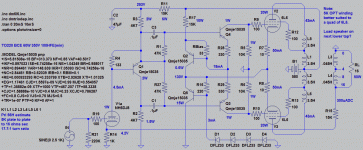
"With Equal Load" yes. The voltages are equal. The impedances are still not.
"With Equal Load" you can't see or hear it, doesn't cause any problem.
This comes back to haunt you when the loads are not equal.
A grid in slight forward conduction, or merely seeing screen voltage begin
to drop due screen current draw is not the same load as other Pentode's
grid that is in deep cutoff.
When the grid connected to the cathode misbehaves, the error will be
forced correct locally, and error will re-appear at the other grid driven
by the anode. Which is fine, cause its in cutoff this half cycle anyway.
When the grid connected to the Anode misbehaves, nothing is corrected.
The error is heard, and no portion of the error is transfered to the cathode
driven side.
OK, not entirely true. There is the 1/Mu portion of the error thats always
on the cathode side...
----
When drives are balanced, half the error is corrected, and half transferred.
and this misbehavior is in symmetry across the middle.
----
Also remember that small errors are aggrivated by the open loop gain.
At that point in the circuit there is no such thing as a small error.
Agh! I tried to prove this in sim with a very slight overdrive. But the global
loop corrected both so much you couldn't tell any difference due to local
impedance mismatches.
Both errors are exaggerated in the drive signal by closed loop correction.
I just totally wasn't expecting both exaggerated errors to look so much
the same?!?!?. Disconnect the global loop to really see them misbehave
differently.
I disabled impedance equalization with a large bypass cap across R1.
Local impedance equalization may indeed by completely meaningless once
the big loop is closed? Maybe this simulated transformer is unrealistically
wideband to draw any hard conclusion that a global loop really fixes all.
Last edited:
Slightly into A2 with no blocking.
Just turn the LTP upside down...
Only 1 pole of caps left to kill?
If transistor voltage gain offends,
R28 R29 can certainly be reduced
to unity gain 10K. Works better if
you let LTP have some gain...
Just turn the LTP upside down...
Only 1 pole of caps left to kill?
If transistor voltage gain offends,
R28 R29 can certainly be reduced
to unity gain 10K. Works better if
you let LTP have some gain...
Attachments
Last edited:
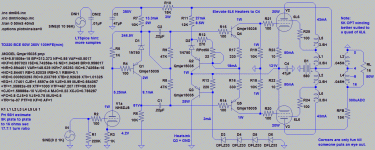
Further tweakage, slightly more A2...
Better sorted ref designators.
Hopefully you can still see Williamson in it?
All that PNP-age and VBE constant current
makes it a little unfamiliar at first glance.
Zeniers further stiffen VBE CCS and can buck
tempcos of well matched emitter junctions.
Don't place too much faith in my tempcos,
I'm just throwing random sand at random.
C2 and R9 aren't absolutely necessary, but
takes a lot longer simulation for DC balance.
If you replace those with a simple wire, you
could get the whole thing down to one cap.
And be at least halfway direct coupled.
Excepting the OPT in the loop of course...
Q3 the only sand that gets hot, also happens
to have a grounded collector (lucky accident).
Could bolt right to star ground lug or something.
T0220 heatsink tab is also the collector.
Fear not 580V, with fixed cathode bias at 130V.
6L6 are seeing only 450V UL. Heaters here will
need to be elevated to voltage at C4, probably
no harm elevate 6DJ8 along with...
Attachments
Last edited:
If R17 were made to be adjustible? Or a pot inbetween R16+R17?
then slightly mismatched pentodes could be biased individually.
AC gains will still be equal across the LTP even if R16 differs from
R17, as CCS provides no leakage path for AC. Yet DC biases can
be purposely imbalanced here to correct a mismatch.
Constant current across Q2 VBE+Zenier becomes bias at R18,19.
Why I threw the Zenier at improving VBE regulation, so the bias
voltage that appears on 6L6 G1's would not drift...
Last edited:
Getting the amp stable with Hammond transformers may prove a challenge- the Williamson is VERY demanding of the transformer bandwidth.
In any case, to reiterate:
1. Nothing in the driver stages needs to be changed when going to 6L6 except compensation.
2. The output stage operating points will have to be altered.
3. The output stage topology will have to be altered to get to 25 watts. UL is a good option. If your heart is set on triode, accept that you'll have 15 watts instead, and that the perceived volume difference between 15 and 25 watts isn't exactly night and day.
If you want further advice on changing out the output stage, it will help if you mention which transformers you're using.
Could you elaborate a little on points 1 and 3? I'm not sure what you mean by compensation and I do not intend to run them in triode.
- Status
- This old topic is closed. If you want to reopen this topic, contact a moderator using the "Report Post" button.

