I'm really happy with my light bulb RCRC power supply trick. I'm using a very small 15W light bulb as the 2nd R in the filter. It just glows, but keeps the voltage to about 250V with the output stage drawing 40mA.
Isn't 40mA too much for this tube? The cathode/filament really lights up at that current. I think that tube is dissipating about 10W.
Isn't 40mA too much for this tube? The cathode/filament really lights up at that current. I think that tube is dissipating about 10W.
I'm really happy with my light bulb RCRC power supply trick. I'm using a very small 15W light bulb as the 2nd R in the filter. It just glows, but keeps the voltage to about 250V with the output stage drawing 40mA.
Isn't 40mA too much for this tube? The cathode/filament really lights up at that current. I think that tube is dissipating about 10W.
From my experiments, if not to exceed 11W on screen+cathode it is fine, anode even does not start glowing.
")
You forgot about R21. You will get R28 + R21 + Rds(1 + gm*R21)
With gyrator as drawn you will get the same resistance that you get from CCS as drawn, that will depend on value R21 and parameters of your particular MOSFET. Of course, add roll-off on lower frequencies.
If I personally go with pentode load on CCS or gyrator, I would first of all increase many times value of R21, and short R28, or at least decrease R28 to the minimal value desired for HF response. Then define amplification factor by a plain linear resistor effectively in parallel on AC. Otherwise you add to your R28 resistive load some non-linear portion of MOSFET resistance.
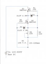
Accurately compute CCS Zout, again:
Zout= Rp x (Mu +1) // Rload // R7 = (300000x10) // Rload // 24000
Rp x (Mu +1) = 300000 x (10) = 3 million
Rlad = 1/Gfs + 6500 = 6507 (data from DN2430; Gfs at 20 mA is 0.14 mA/V)
Now we have:
Zout = 3 million // 6507 // 240000 ~ 6596.9 ohm.
We can conclude; Zout with CCS have same value as CCS output resistor.
But it is not so important.
I had the opinion that DIYers better known fundamentals tube amplifiers.
Can I use only one SSHV2 to power all four tubes? if yes have I to adjust SSHV2 to 140mA?
No, you only need the SSH2's for the output tube one for each channel.
You should prefilter the SSH2 with CLC, then pull from before the SSHV for the driver ccs/gyrator.
There is little gain and too much to ask the SSHV2 to supply both the driver and output and it is not needed with a ccs/gyrator load.
I run a huge heatsink on my headphone WE417 spud amp (20mA per channel) and the SSHV's still get the heatsink very hot. Trying to run the SSHV2's much over 100mA total is asking for one ugly tube amplifier
Thanks for support regal, so I have to adjust SSHV2 for 80mA (60mA for 4P1L & 20mA for the reg) for the two output tubes, for the CCS I have some DN2540 laying around so I will do the same CCS like SSHV2 but p2p, how have I to calculate the input voltage to have an output voltage of 250V or how many volts draws the CCS? I need to make two CCS: one per each tube driver, right?
Attachments
Last edited:
Thanks Wavebourn. True, I didn't see any glow on the plates - but I think I'll back them down to 8W and see how that goes. Might crank it up later.
It's fun to see the changes on a DH tube. Running the filament alone at 4.2V the tube just gets warm. Somewhere around house cat temperature. Running current thru the tube really lights things up. I never had a separate filament supply on direct heated tubes, so never seen the changes before.
It's fun to see the changes on a DH tube. Running the filament alone at 4.2V the tube just gets warm. Somewhere around house cat temperature.
Running current thru the tube really lights things up. I never had a separate filament supply on direct heated tubes, so never seen the changes before.4P1L_pentode to 4P1L_triode
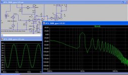
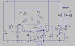
Just answer on some questions derived from pentode driver lovers.
Quick simulation says yes, 4P1L in pentode mode can drive 4P1L in triode mode. It is very easy.
Stay with CCS, reduce Rsurce value, reduce the number of red Leds in string and reduce Ug2.
4P1L in triode mode on output have Ugk around 15-16V.
We need 15Vrms (42Vpp) from driver stage. If Vin=2Vrms, total MU of driver stage must be 7,5.
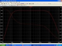
If use 5K:8 OPT with about 15 henrys in primary, You can get about 1.8 Wrms output power with 2.3% THD and Fb 12Hz-84KHz @ - 3dB.
My recommendation is run away from any feedback in two stage SE amplifier. It's very bad. And of course, use well regulated PSU for Ug2 voltage.
Cheers,
Rajko
Just answer on some questions derived from pentode driver lovers.
Quick simulation says yes, 4P1L in pentode mode can drive 4P1L in triode mode. It is very easy.
Stay with CCS, reduce Rsurce value, reduce the number of red Leds in string and reduce Ug2.
4P1L in triode mode on output have Ugk around 15-16V.
We need 15Vrms (42Vpp) from driver stage. If Vin=2Vrms, total MU of driver stage must be 7,5.
If use 5K:8 OPT with about 15 henrys in primary, You can get about 1.8 Wrms output power with 2.3% THD and Fb 12Hz-84KHz @ - 3dB.
My recommendation is run away from any feedback in two stage SE amplifier. It's very bad. And of course, use well regulated PSU for Ug2 voltage.
Cheers,
Rajko
Attachments
No, you only need the SSH2's for the output tube one for each channel.
You should prefilter the SSH2 with CLC, then pull from before the SSHV for the driver ccs/gyrator.
There is little gain and too much to ask the SSHV2 to supply both the driver and output and it is not needed with a ccs/gyrator load.
I run a huge heatsink on my headphone WE417 spud amp (20mA per channel) and the SSHV's still get the heatsink very hot. Trying to run the SSHV2's much over 100mA total is asking for one ugly tube amplifier
Tango NP-126 can be OK for headphones OPT transformer?
Yes, that's what I'm finding on mine. I get a gain of about 10 on the triode output stage using a 5K load (5K:8R). I figured a similar voltage for the grid. I'm using battery bias.4P1L in triode mode on output have Ugk around 15-16V.
We need 15Vrms (42Vpp) from driver stage. If Vin=2Vrms, total MU of driver stage must be 7,5.
I will, however, use a bit of GNFB. I am not afraid! Having seen and heard what a mild amount (~6dB) of FB can do for most SETs, I'll be giving it a try.
Just answer on some questions derived from pentode driver lovers.
Quick simulation says yes, 4P1L in pentode mode can drive 4P1L in triode mode. It is very easy.
Stay with CCS, reduce Rsurce value, reduce the number of red Leds in string and reduce Ug2.
4P1L in triode mode on output have Ugk around 15-16V.
We need 15Vrms (42Vpp) from driver stage. If Vin=2Vrms, total MU of driver stage must be 7,5.
If use 5K:8 OPT with about 15 henrys in primary, You can get about 1.8 Wrms output power with 2.3% THD and Fb 12Hz-84KHz @ - 3dB.
My recommendation is run away from any feedback in two stage SE amplifier. It's very bad. And of course, use well regulated PSU for Ug2 voltage.
Cheers,
Rajko
This is why the 4p1l driving another 4p1l is such an attractive proposition. And if you have a balanced source an input transformer can even drive a 2A3 with a 4P1l. Want more? balanced source -input xfomer- 4p1l -1:2 interstage -300B. All DHT two stage tube 300B SET! Its such a fabulous tube.
Tango NP-126 can be OK for headphones OPT transformer?
I am a headphone amp transformer pessimist, I don't think any off the shelf OPT's are really suited for headphones, You really have to custome order and it gets expensive, even then there are issues. All depends on your expectation level of course.
Hope is that transformer outfits will see the error in there ways and start offering OPT's designed from scratch for headphones. And then the other issue is the impedances and efficiencies of different model headphones vary exponetially model to model that it turns into a very frustrating dive.
I've had the output stage of my amp running for a few days - hoping to finish up the input section this weekend. The output stage sounds great driven by a simple line level signal. Not very loud, of course, but clean and nice. Works great for headphones.
I'll try to get some harmonic distortion plots and post them here.
I'll try to get some harmonic distortion plots and post them here.
You do not give me very much spirit to do the headphones amp. Transformers are expensive so if I'm not sure I don't wanna lose the money, I will keep wiht my OTL hadphone amp.
Well even the basic Electra-Print SET transformer sounds better than a OTL+ cap so I don't mean to be that pessimistic, its just that you must have a pair that you like and want to live with because another model won't work due to impedance mismatch. There is real magic with SET for headphones its just more expensive than building a preamp.
This is why the 4p1l driving another 4p1l is such an attractive proposition. And if you have a balanced source an input transformer can even drive a 2A3 with a 4P1l. Want more? balanced source -input xfomer- 4p1l -1:2 interstage -300B. All DHT two stage tube 300B SET! Its such a fabulous tube.
Yes. 4P1L as a driver have unlimited possibilities. This tube is a miracle.
Pentode driver for 300B you can see in my post no. 396 of this thread.
Will try it in my 300B SET when I get in this tube, and when I have more time.
Rajko
Since headphones need very little power and not a lot of voltage, what sort of output would you want from a headphone specific OPT?
This is actually a common misconception. For example the hottest high-end headphone right now is an HE-6. It takes a serious 6Watts at 50 ohms. Thats more voltage swing than a 35 watt amplifier. Only a 1000V GM70 SET can deliver that sort of Voltage Swing properly. They are really a ss amp only type of headphone.
For senns they are efficient so you may be able to get away with a 5k:300 preamp OPT. Just watch the secondary DCR, a 300 ohm secodary can kill your damping factor and power transfer.
Even 32 ohm 97db/mw headphones are a problem, I had a pair of custom electraprint 5k:32. Secondary DCR is 12 ohms
So I am losing 1/3 of my power down the drain, if I had known that I wouldn't have designed my SET around a we417.I guess what I am trying to say is make sure you love your headphones cause you have to build the SET amp for the specific model and start with the OPT. Its very difficult to build a one size fits all.
With speakers sometime in the 60's all the manufacturers got together and said "we will make 8 ohms the standard" at the same time headphones were all standardized to a 120 ohm "tap", but the last decade that standard has been thrown out the window. So designing an amp for headphones is really tougher than speakers (if you want the best.)
Main thing is define your scope of work, the beauty of DIY is we can build to match. I definately think the 4P1l would be an ideal output tube for senns, just finding the right OPT will take some legwork, but it should be able to serve double duty as a preamp.
regal how many mA needs the Senns?
Wich one Sowter is more suitable for HD600?
TRANSFORMERS FOR HEADPHONE AMPLIFIERS
For preamp I will need other transformer like the Lundhal LL1660 that I have purchased for #26 preamp, right?
Summarizing what are the necessary best spec for HD600:
-application SE
-ratio
-primary impedance in ohms
-secondary impedance in ohms
-primary inductance in Henry
-power in watts at 50Hz
-DC mA
-core
Last edited:
For headphones, you need to figure out how much voltage swing you want and see whether a custom transformer is necessary. If you need less than 12Vrms, then a standard speaker transformer is the way to go. Some have 16 ohm taps.
Part of the tube sound comes from the transformer. It fattens up the waveform slightly, which gives warmth and soundstage expansion (very desireable for headphones), while being much quicker-sounding than a big electrolytic cap. I would describe a transformer as transparent but slightly colored, while capacitors are neutral but not transparent. For preamps and headphone amps, I much prefer transformer-coupled.
Part of the tube sound comes from the transformer. It fattens up the waveform slightly, which gives warmth and soundstage expansion (very desireable for headphones), while being much quicker-sounding than a big electrolytic cap. I would describe a transformer as transparent but slightly colored, while capacitors are neutral but not transparent. For preamps and headphone amps, I much prefer transformer-coupled.
- Home
- Amplifiers
- Tubes / Valves
- One more 4P1L SE