Lookin' Good!
Thanks!
There will be also tubes for MM and MC phono stages (4 on top, 2 underneath)
Phono input will be switchable between MM and MC. For MC will be used input transformers and 6S17K-V input tubes.
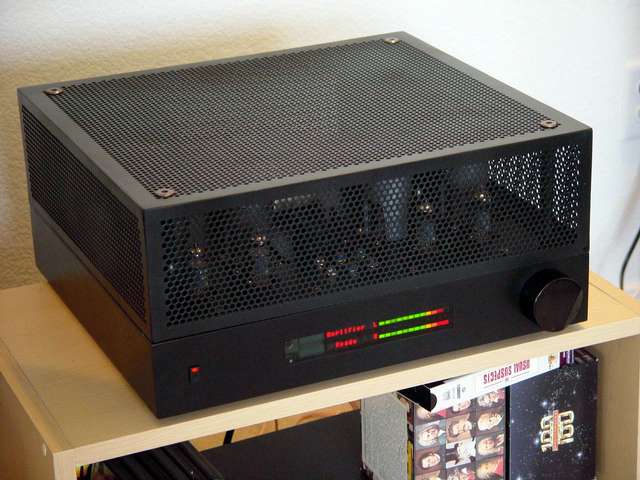
A little bit more of bodywork (click the image to expand it):
An externally hosted image should be here but it was not working when we last tested it.
Nice!!!
Thanks!
There will be also tubes for MM and MC phono stages (4 on top, 2 underneath)
Phono input will be switchable between MM and MC. For MC will be used input transformers and 6S17K-V input tubes.
I'd say it is a very safe bet that you are pleased with the sound and performance of this amplifier. I hope to get started on my own design in the near future, looking forward to getting it done - first though I have to finish the GM70 amps..
I was fantasizing about the same 4gu50 tube PP. Although a 2 tube PP would look better I guess and 100W is only 3 db less than 200W.I am working in parallel on 2x200W tube amp using GU-50 tubes.
B+ will be 1 KV well regulated.
Last edited:
I was fantasizing about the same 4 tube PP. Although a 2 tube PP would look better I guess and 100W is only 3 db less than 200W.
Mine will be 250W limited by an optical peak compressor on 200w.
Mine will be 250W limited by an optical peak compressor on 200w.
Quite a contrast with the 4p1
Quite a contrast with the 4p1
Yep, for a little bit higher number of listeners.
A east europe gu50 PP.
Nice box!
Here is one of my versions:
Attachments
Last edited:
Анатолий, amazing!!
Thank you Никола!
Last edited:
I wonder, how good is adhesion of mirror finish to Lexan: I think about gluing the plastic mirror between hot toobs and transformers, so no bolts would be visible...
Any experience?
Try this stuff: 3M Transfer Tape 467MP
I use the 2.0 mil stuff (200MP) to apply anti-rattle plates to brake pads. They haven't moved yet.
3M? Adhesive Transfer Tape 467MP
Regards, KM
Quote:- "Now I need to make that +12V stabilizer, and increase voltage of the negative stabilizer."
How about using 7 x cheap red LED's @ around 10mA?
Also, do you have an updated schematic and if so, would you please post it?
The schematic is still the same, except 6J9P trioded instead of 6N16B paralleled, and one more 4P1L in parallel to the existing one (including filament voltage drop resistor and bias control resistor), and 2K4 transformer instead of 5K transformer.
Speaking of 3'rd grid bias, I decided to go without it, since 1'st drive by cathode follower is adequate.
I thought you said 3rd grid bias increased linearity? Or was it an insignificant difference?
It increased linearity with less positive 1'st grid drive needed, but requires higher negative bias of the 1'st grid. The amp sounds nice without this trick, so I decided not to deal with such complications: I have limited negative voltage supply. May be I will try it later, carefully measure and compare results.
OK, thanks for the explanation. Will you run measurements on the amp eventually?
Yes!
But before that, I have to finish input selector, attenuator, remote control, and phono stage.
By the way, here is a rear panel: speaker outpurs, 4 switchable inputs in the left corner, and in the right corner inputs for MC and MM, with a switch between them. I decided to use a 5-pin female XLR for MC input. MC input will be balanced.
Do you know if some standard for XLR inputs for MC phono exist?
Do you know if some standard for XLR inputs for MC phono exist?
An externally hosted image should be here but it was not working when we last tested it.
Last edited:
- Home
- Amplifiers
- Tubes / Valves
- One more 4P1L SE