Pin FunctionBy the way, here is a rear panel: speaker outpurs, 4 switchable inputs in the left corner, and in the right corner inputs for MC and MM, with a switch between them. I decided to use a 5-pin female XLR for MC input. MC input will be balanced.
Do you know if some standard for XLR inputs for MC phono exist?
An externally hosted image should be here but it was not working when we last tested it.
1 Chassis ground (cable shield)
2 Positive polarity terminal (hot)
3 Return terminal[4] (cold)
Attachments
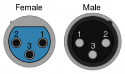
Pin Function
1 Chassis ground (cable shield)
2 Positive polarity terminal (hot)
3 Return terminal[4] (cold)
Thank you Helmuth;
I mean 5 pin XLR for balanced stereo ins from MC head.
Nooks like no standard exist, so I will invent mine.
Do you know if some standard for XLR inputs for MC phono exist?
These are the common ways they are hooked up
3 pin 1 gnd 2 hot 3 return
4 pin 1 gnd 2 return 3 in between 4 hot
5 pin 1 gnd 2 return L 3 hot L 4 return R 5 hot R
or 5 pin 1 gnd 2 hot in 3 return in 4 return out 5 hot out (prevents feedback)
6 pin 1 gnd 2 return A 3 hot A 4 return B 5 hot B 6 unbal in
ES
5 pin 1 gnd 2 return L 3 hot L 4 return R 5 hot R
Thank you Simon!
A month ago local audiophiles were impressed by sound of this amp.
We used this speakers to try it:
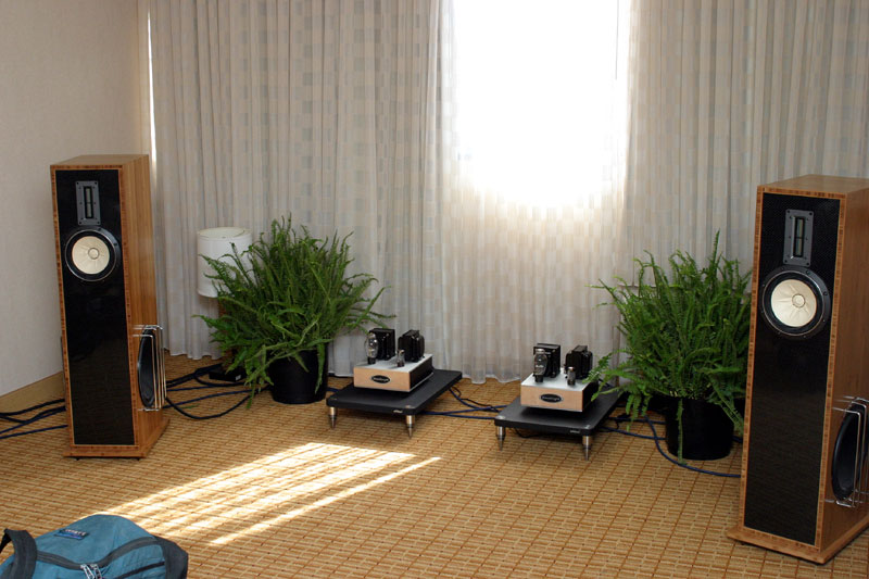
The sound was very natural, clean and detailed. However, such speakers require at least 10W of power to be happy, but for more effective speakers it is the killer amp.
Edit: despite of common beliefs, audiophiles absolutely did not react on presence of semiconductors and absence of an interstage transformers. They did not ask about resistors and capacitors. They asked about tubes and transformers, though, demonstrating understanding of linearity, smoothness, distortions (non-linear and frequency & phase response). All attention they paid on sound quality.
We used this speakers to try it:
The sound was very natural, clean and detailed. However, such speakers require at least 10W of power to be happy, but for more effective speakers it is the killer amp.
Edit: despite of common beliefs, audiophiles absolutely did not react on presence of semiconductors and absence of an interstage transformers. They did not ask about resistors and capacitors. They asked about tubes and transformers, though, demonstrating understanding of linearity, smoothness, distortions (non-linear and frequency & phase response). All attention they paid on sound quality.
Last edited:
I need a little help with a 4P1L line stage I am building. From the various plate curves I've seen I'm aiming at roughly 150 volts plate, 15 ma and -15 volts bias. The plate load is a a couple of cascoded DN2540's per channel similar to
Tube DIY Asylum - RE: Hooked up the Ixys IC CCS tonight - preliminary results - Tre' - July 11, 2009 at 22:13:45
The output of the ccs is connected to pins, 2, 3, 4.
The mu output of the ccs connects to a 2uf cap and thence to the output rcs socket.
I'm using a regulated 3.9 volt DC supply to power the heaters (pins 1 & 7). The supply is floating (simple LM317 to start with). I've got a 47uf cap across pins 1 & 7.
I've got a 1k cathode resistor to ground from pin 8. I figure that should give 15 volts bias at 15 ma.
The heater supply is working as I expect.
I've got 280 volts on top of the CCS. There is about a 10 volt drop across the ccs with about 270 volts on the plate, obviously not what I want.
I'm not getting any bias voltage from pin 8 to ground which is where I'm expecting about 15 volts. Same in both channels, so I presumably have wired something incorrectly.
Any ideas?
ray
Hi Ale;
220V A-K, -17V G1-K, 50 MA per tube. 5 W from paralleled pair. They are easy to parallel due to linearity and consistence.
Edit: sorry for late answer, I was in Az, at Grand Canyon then, and have not seen your posting.
May I add your graph to my page?
Hi Anatoly,
Congratulations for this superb design. I'm sure you're enjoying it!
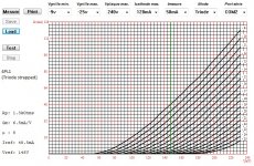
I've traced the 4P1L triode strapped anode curves (see attached).
What is the bias point in your design?
220V A-K, -17V G1-K, 50 MA per tube. 5 W from paralleled pair. They are easy to parallel due to linearity and consistence.
Edit: sorry for late answer, I was in Az, at Grand Canyon then, and have not seen your posting.
May I add your graph to my page?
Last edited:
I need a little help with a 4P1L line stage I am building. From the various plate curves I've seen I'm aiming at roughly 150 volts plate, 15 ma and -15 volts bias. The plate load is a a couple of cascoded DN2540's per channel similar to
Tube DIY Asylum - RE: Hooked up the Ixys IC CCS tonight - preliminary results - Tre' - July 11, 2009 at 22:13:45
The output of the ccs is connected to pins, 2, 3, 4.
The mu output of the ccs connects to a 2uf cap and thence to the output rcs socket.
I'm using a regulated 3.9 volt DC supply to power the heaters (pins 1 & 7). The supply is floating (simple LM317 to start with). I've got a 47uf cap across pins 1 & 7.
I've got a 1k cathode resistor to ground from pin 8. I figure that should give 15 volts bias at 15 ma.
The heater supply is working as I expect.
I've got 280 volts on top of the CCS. There is about a 10 volt drop across the ccs with about 270 volts on the plate, obviously not what I want.
I'm not getting any bias voltage from pin 8 to ground which is where I'm expecting about 15 volts. Same in both channels, so I presumably have wired something incorrectly.
Any ideas?
Hi Ray;
it looks like you've got absolutely dead tube. Even with 3.9V on filament instead of 4.2V it should draw enough of current.
Hi Ale;
220V A-K, -17V G1-K, 50 MA per tube. 5 W from paralleled pair. They are easy to parallel due to linearity and consistence.
Edit: sorry for late answer, I was in Az, at Grand Canyon then, and have not seen your posting.
May I add your graph to my page?
Hi Anatoly,
Sure, no problem and let me know if you the resolution is low. Thanks for your response. I'm very tempted to work on a similar design once I complete my current 45 SET.
Thanks,
Ale
https://picasaweb.google.com/azazello52/Amplifiers#5594368832947255474
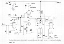
This is my SE 4P1L & PCC88 Siemens & OT Hammond 125FSE & Interstage transformer Hammond 124B. I made it for very short time /but adjustment was about 2 weeks/ and
I participated in DIY meeting 2011 in Goteborg - Sweden. I'm glad that people
interested and I showed my schematic to some guys, that liked my SE.
Hi Azazello,
Can you share for me schematic of 4P1L & PCC88 Siemens? I intend to DIY 4P1L SE and I am looking for schematic.
Thanks
Of course.....The schematic is on the bottom:
HiFiForum.nu - DIY 2011 bilder
HiFiForum.nu - DIY 2011 bilder
Thank you very muchOf course.....The schematic is on the bottom:
HiFiForum.nu - DIY 2011 bilder
A couple of questions:-
1) More or less what RMS drive-voltage is required to drive a parallel 4p1l output stage with edcor GXSE15-6-2.5k trafos into 6 Ohm speakers to max power please?
2) I am thinking of using a mosfet source follower as a driver, direct coupled to 4P1L outputs. I think it will be cheaper, easier to implement and easier to get good results with than a cathode follower. Any comments?
Last schematic, attached
Hi Wavebourn,
I'm very interesting on your you shared useful information about russian loctan base tube. I wonder that if you have been tried the 2P29L yet?
Regards
Telefunken designed again, for their German army... Captured from enemy by Red Army, then used for themselves in a bit different envelope. The story is similar to GU-50. Also, one more remarkable tube with similar fortune is 12P17L. Almost like 4P1L, but with more convenient 12.6V indirectly-heated cathode, and fully enclosed in aluminium shield.
Интересно проводили эксперименты с 12П17Л-очень интересно?

English please Vmelan.
It is interesting to have experimented with 12P17L, very interesting?
- Home
- Amplifiers
- Tubes / Valves
- One more 4P1L SE