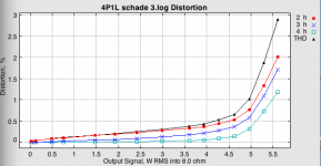
What's causing 3HD to increase faster than 2HD nearing 3W output? Is that normal for a 4P1L getting near clipping? Maybe the onset of grid current?
I was thinking a DN2540 or similar could be used as a phase splitter (concertina), given a voltage amp with enough current to get past its input capacitance.
--
I was thinking a DN2540 or similar could be used as a phase splitter (concertina), given a voltage amp with enough current to get past its input capacitance.
--
Last edited:
I will post the anode curves when I get the chance but the wider the signal is spread out is exposed to curves not that evenly spaced. This spice model doesn't include a proper grid current model so you should expect more grid current to kick in and higher third order distortion as a result.
Haven't built this, so can't comment on the sound. Albeit, MK liked his original version based on 6L6. Perhaps a paralleled pentode is worth trying for more power. But on this case I'd look for a bigger pentode instead.
Haven't built this, so can't comment on the sound. Albeit, MK liked his original version based on 6L6. Perhaps a paralleled pentode is worth trying for more power. But on this case I'd look for a bigger pentode instead.
When added the blue, red and green curves exeed the value of the black curve. How can that be?Nope. See legend. It's THD. Blue and red are 2nd and 3rd harmonics")
You don't sum them up directly, Wikipedia for you: http://en.m.wikipedia.org/wiki/Total_harmonic_distortion
Perhaps a paralleled pentode is worth trying for more power. But on this case I'd look for a bigger pentode instead.
Maybe GU-15 or 6P21S?
You don't sum them up directly, Wikipedia for you: Total harmonic distortion - Wikipedia, the free encyclopedia
Ale, I hate to be nit picking but it seems your software is comparing harmonic powers to the fundamental power, so these numbers should add up. A better method for obtaining data would be the ratio of harmonic amplitudes to the fundamental amplitude. Outcomes differ but I guess it's for the sake of the argument not that interesting..
Here it goes with a pair of paralleled valves. OT was wired down to 3K:8. You can get 5W at 1% THD. Interesting to see how the harmonic spectrum has changed as dialled the feedback resistor (R6). A stronger H2 component in this case. Very tempted to build a breadboard and listen to it
Ale
Ale
Attachments
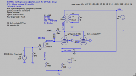
Does anyone have any idea about how to calculate the feedback factor on this circuit?
In my view, the impedance looking at the drain of the DN2540 should be quite high and approximately Rout=gm*rds*Rsource, correct?
If that is the case the voltage at the grid should be Rout/(Rout+R6) *Vanode?
DN2540 parameters vary wildly and have seen in Morgan Jones' book that rds is close to 30k and gm can go from 20mA/V to 150mA/V depending where you stand in the operating point.
Ale
Hi Ale,
You can get a sense of the DN2540 dynamic parameters from the "Typical Characteristics" Curves.
Check first the "output characteristics" graph, and see how Id varies from 10V to 400V (with Vgs constant). It is certainly higher than 40K, and probably a lot higher, but this applies only at dc.
At higher frequencies, the high capacitance of MOSFETs shunts current, though the curves only give values for Vgs = -10V. Real operating conditions, like your -1.4V, will yield much more. Also, factor in the input capacitance of the 4P1Ls.
gm falls quickly with Id, and is very low at Id = 1.3mA - 20mA/V or less, as shown on the curves (nice to have this curve, rarely seen for power FETs).
If Michael's design is based around 6L6 and possibly a different FET, you'll need to find out how the feedback mechanism is designed to work, since it may depend on the FET type and the drain current.
Hi Rod,
Thanks for that. I looked at the curves briefly before posting and struggled to derive any gm/rds information given the low bias point of the FET in this circuit. I could post here Morgan Jones' traced curves for discussion but not sure if that would be appropriate given copyright, etc.
I certainly agree that gm is quite low, possibly 20mA/V or less at 1-2mA and that rds will be higher but not as high as +500k-1M when VDS>100V and higher vgs values. Hard to derive from the output characteristics curves given scale of ID and VDS.
The circuit compared to Michael's is the same. Only difference is that he is using an IXTP01n100d (1000V depletion mosfet) running at 5mA which I don't have the spice model. My version doesn't need to run at higher voltages like the 6L6, so the DN2540 should be good. In fact, an LDN150 could work as well here.
Is my logic about the feedback ok and the equation to derive it?
Thanks
Ale
Hi Ale,
Yes, you will need tracer curves, because the "Rd" (delta-Vd/delta-Id) is FET process dependent.
I would not expect to derive it from gm (other than the fact that gm and Id are related).
So you could use tracer curves to assess Rd (** at a given Id **), and that will suffice. Might be wise to look for sample-to-sample variation, too.
But beware, the effective Rd needs to be stable over the full swing of your signal, so please check for that when inspecting the curves.
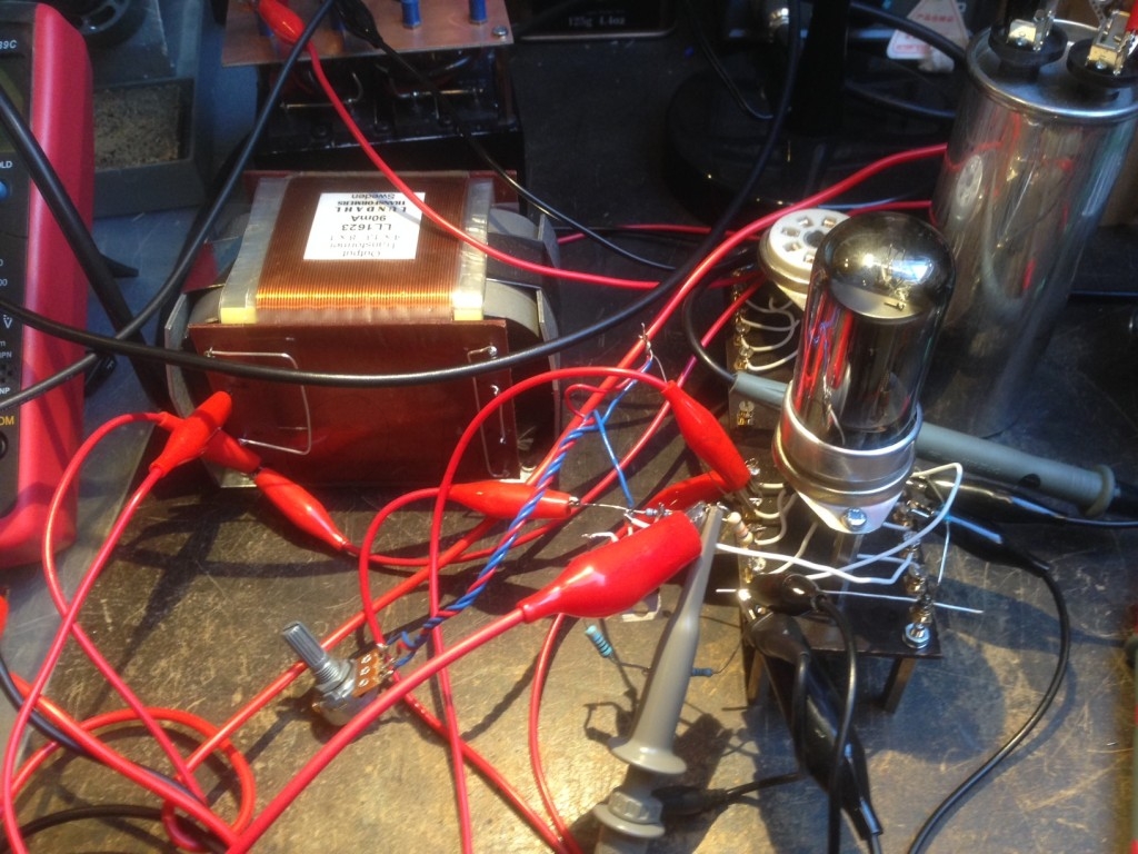
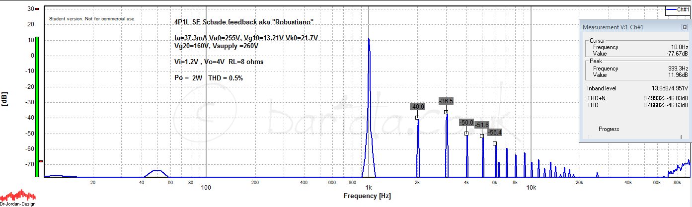
I couldn't resist the temptation and did a quick breadboard of the single-ended 1 x 4P1L circuit. Interesting results after increasing the screen voltage to 160V and dialling the feedback resistor with a potentiometer. 2W at 0.5% is not bad at all and very close as the simulation. I like the harmonic distribution. Lowest distortion is achieved closely to the point it turns back to pentode mode:
Ale
Ale
No, I don't have the spectrum captured in triode mode. I do have many of 4P1L as driver but with different load. Either way I wouldn't expect to be that different from the latter, which had a nicer H2 component. I will see if I can re-wire this breadboard and do a quick comparison.
Ale
Ale
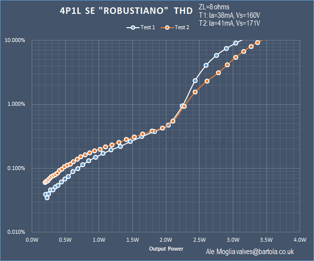
Here are some further tests using automated measurements. Firstly I tried same configuration running the 4P1L at closely 38mA and 160V screen voltage. Second test, I dialled up the screen voltage to 171V and tweaked feedback to get current up to 40mA
Interesting to see that the performance is more triode-like and has a higher THD at lower output levels, however at higher levels the THD is lower. Mainly dominated by H3 and significant rise of H5 given grid current I suspect:
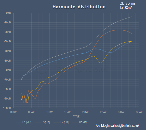
Here is the harmonic distribution of the first test (more pentode like)
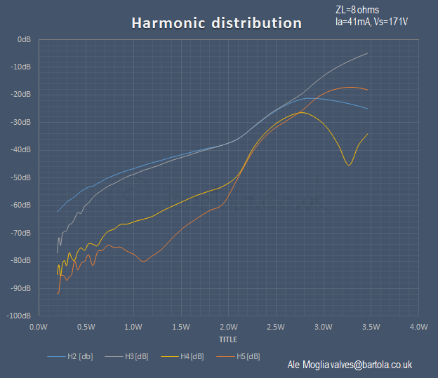
Here is the harmonic distribution of the second test (more triode like):
From a frequency response perspective, it performs very good with -3dB from 10Hz to up to 35kHz at 1W tested level:
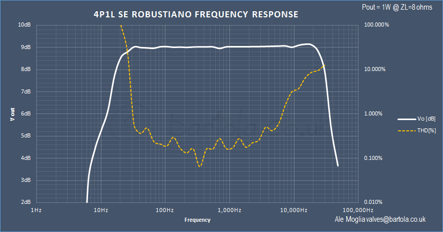
What surprised me was to find out the increasing distortion at HF. Will this be due to the 4P1L grid capacitance or the DN2540?
Any ideas?
cheers,
Ale
Interesting to see that the performance is more triode-like and has a higher THD at lower output levels, however at higher levels the THD is lower. Mainly dominated by H3 and significant rise of H5 given grid current I suspect:
Here is the harmonic distribution of the first test (more pentode like)
Here is the harmonic distribution of the second test (more triode like):
From a frequency response perspective, it performs very good with -3dB from 10Hz to up to 35kHz at 1W tested level:
What surprised me was to find out the increasing distortion at HF. Will this be due to the 4P1L grid capacitance or the DN2540?
Any ideas?
cheers,
Ale
- Home
- Amplifiers
- Tubes / Valves
- One more 4P1L SE