
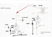
Thanks for cleaning up my skimpy schematic, but 150V B+ is much too low.
Good operating point for this tube is 200-230V 30mA.
So that means you have a B+ of about 275V for the first tube with the CCS or gyrator, then use an extra RC to give the 200V B+ for the second tube.
I have 4 of the 4p1l's and am determined to build this when I finish this DAC B.S. But I am on the fence between Grados, Senns, and Orthos. So something to keep in mind when you buy your transformer is you might not want to be tied down to only a 300 ohm tap.
Also to add confusion if you read the ecp article linked above about parafeed, you will really get frustrated cause finding a permalloy core custom para-feed transformer is impossible.
A high quality permalloy 5k:300+32 parafeed OPT would be a real nice to have for preamp builders because it would give a nice headphone output. Kill two birds with one stone.
Can I use only one SSHV2 to power all four tubes? if yes have I to adjust SSHV2 to 140mA?
Attachments
Last edited:
Can I use only one SSHV2 to power all four tubes? if yes have I to adjust SSHV2 to 1440mA?
SSHV2 is good for about 100 mA
SSHV2 is good for about 100 mA
Yes max current 100mA, so I will need two SSHV2 one for each channel, but the question is can I do it like the last attached pic?
Hi Rajko,
I've done some experiments on this. As Anatoliy said, you need to compensate the high ra of the pentode with the high impedance of your CCS or gyrator load otherwise gain is way too much and circuit is unstable. A way of doing this is to add a parallel resistor with the anode as suggested by Gary Pimm.
Here's some examples of my tests, you may still want to reduce the load resistor value as gain is too much in my opinion...
http://www.bartola.co.uk/valves/2013/01/13/4p1l-pentode-driver-continued/
Cheers
Ale
Definitely need negative feedback, otherwise amplification will be excessive and frequency dependent. Like in opamps, where VAS stage is loaded on CCS.
Yes, especially the frequency dependent part is troublesome.
Do you think C3G in pentode mode would not have the same problems?
Absolutely not.
But perhaps we will again discuss about 4P1L in pentode mode.
First, I have to get them.
Guys,
That is bad information for me.
In this case, 4P1L cannot replace pentode drivers C3g or C3m in my existing 300B and 6C33C SETs.
It does not matter which pentode, actually. All have pentode curves that are different from triode curves.
You may try also 6P15P pentode.
It does not matter which pentode, actually. All have pentode curves that are different from triode curves.
You may try also 6P15P pentode.
Anatoly, please ...
STAGE gain in my ideas presented here is ~28. With 2Vrms at input, you have 56Vrms (78,5Vp or 157Vpp) of voltage swing . It is quite enough for drive most output triodes.
Zout of gyrator...I dont know. I have no experience with gyrator, I said.
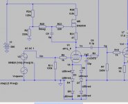
Back to my post No.396 ie. 4P1L loaded with CCS.. Output impedance is (very roughly) Rp x MU in paralel with Rload
R load should be 1/Gfs (of DN2530 at 20mA) + 6K5 (R21).
From DN2530 data, Gfs is 0.14 mA / V.
All in all, Zout (with CCS) is ~~ 7-8kohm.
This calculation, based on simulations, shows ... 4P1L in pentode mode should be the very good driver for a lot of output tubes.
It's to late here, I'm going to sleep.
Goodnight
You forgot about R21. You will get R28 + R21 + Rds(1 + gm*R21)
With gyrator as drawn you will get the same resistance that you get from CCS as drawn, that will depend on value R21 and parameters of your particular MOSFET. Of course, add roll-off on lower frequencies.
If I personally go with pentode load on CCS or gyrator, I would first of all increase many times value of R21, and short R28, or at least decrease R28 to the minimal value desired for HF response. Then define amplification factor by a plain linear resistor effectively in parallel on AC. Otherwise you add to your R28 resistive load some non-linear portion of MOSFET resistance.
Last edited:
- Home
- Amplifiers
- Tubes / Valves
- One more 4P1L SE