I'm finishing up the power supply and I need to put in a bleeder resistor. Someone told me to go with 200K and I wondered if I just put it at the last cap to ground? Also from what I've read in other posts that seems very high value. If someone could confirm to correct it I would appreciate it.
Since this is an unregulated supply would that bleeder resistor factor in in any way as to the final resistance which sets the voltage? The resistor in the end of the power supply duplicates the tube/OT resistance.
Since this is an unregulated supply would that bleeder resistor factor in in any way as to the final resistance which sets the voltage? The resistor in the end of the power supply duplicates the tube/OT resistance.
Attachments
Last edited:
A bleeder has a few purposes. One is safety, so you may want to use a value that causes the voltage to drop to a safe value within about 10 seconds. Another is reduction of unloaded voltage to protect the filter capacitors etc. I would put it across the largest filter capacitor and yes, it is part of the circuit all the time and needs to be figured in with whatever else is in there.
Another use is to improve regulation, namely the difference between full and minimum load voltages. I don't think this use applies in your situation, since your load is probably relatively constant.
Another use is to improve regulation, namely the difference between full and minimum load voltages. I don't think this use applies in your situation, since your load is probably relatively constant.
A bleeder has a few purposes. One is safety, so you may want to use a value that causes the voltage to drop to a safe value within about 10 seconds..
I waited 10 seconds for my amp to discharge, grabbed a component and got a huge shock. I forgot to turn it off !
I dont work on valve amps very often, my nerves wont take it lol
If C2 is the place and this will become what is essentially R1 @200K (2W) that really screws up my calculations since I based it all on the present value of R1. Ugh.
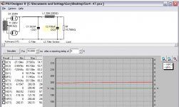
I have all the bits in place after 5 months of pulling it all together. I will have to really play with C1 to get the voltage up to 200V like the schematic.
I have all the bits in place after 5 months of pulling it all together. I will have to really play with C1 to get the voltage up to 200V like the schematic.
Thanks! Will that allow me to figure out C1?
No, but it will let you find a realistic value for the bleed resistor
I keep coming up with negative numbers.
when using that great tool.
I can't figure why...
Whats your input data? Screen shot would be good
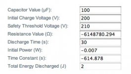
I haven't used that particular piece of software. I usually just do the math. But I would guess that the safety threshold voltage is the voltage where you consider the circuit to be safe to touch. It should be less than the starting voltage. I'd put 5 V or so.
Or do the math... TimeConstant = R*C. The cap is discharged after five time constants.
So: DischargeTime = 5*R*C --> R = DischargeTime/(5*C).
R in Ohm, C in Farad, time in seconds.
The software probably uses the equation for exponential decay, but I don't see a point of calculating it to that level of accuracy. If it takes 30 or 31 seconds to discharge, would you notice?
As far as the position of the bleeder goes. Place it where it will discharge all supply caps in the amp. Also remember to use a resistor that can handle the power. P = E^2/R. E is the nominal DC voltage on the cap. I usually use a margin of 4~5x, so I'd go with a resistor that can handle at least 4~5*P.
I also noticed that you use 350 nF as your first cap. That's tiny. The 5AR4 will handle up to 50 or 60 uF if I recall correctly (check the datasheet). I suggest using 22 uF or 47 uF. You'll get much less supply ripple that way.
~Tom
Last edited:
Tom. I tried 5V as the safety and still got negative numbers. I'm bad at math but admire those who know it well.
This is supposed to be a choke loaded tube rectified so I'm just using the first Cap to set voltage. I won't know exactly what it will be until I actually wire it up and see how it performs.
This is supposed to be a choke loaded tube rectified so I'm just using the first Cap to set voltage. I won't know exactly what it will be until I actually wire it up and see how it performs.
nice math Tom, but you can't beat the advance of javascripting!
The script I linked to works fine. Enter your values in the first four boxes, tabbing between them. When you tab from the last entry (resistance value) the script automatically recalculates the missing values.
As an aside, the further down the CRC chain you put the bleeder, the lower power handling capacity it requires since the majority of the current is being pulled through the dropping resistors in the CRC chain...
Last edited:
- Status
- This old topic is closed. If you want to reopen this topic, contact a moderator using the "Report Post" button.
- Home
- Amplifiers
- Tubes / Valves
- Best position for bleeder resistor?