Ok, let's admit it. I'm getting a bit undecisive. I have this self-inverting push-pull thing called "Sika" (the Pig in finnish - a project needs a name) in the works. Actually it has been in the works for a long time. I was planning on an E83F pentode mode input working to a 5687 CF direct coupled and a self inverting push-pull powerstage with EL34:s in triode. I scrapped the whole design. For reasons.
I'm working with the following conditions:
The idea is to get something between 5-10 watts out. I don't need power. Right now I have a E55L SPUD amp delivering probably under 500 milliwatts to my Fostex/Eminence open baffle speakers, and it's loud enough for background listening. I basically need a watt or two.
So I was going to go with a pair of 6V6's in triode mode, and I want to drive it with a 6SL7, because I have a box full of NOS lying around. Alternately ECC81 driving EL84's would also be acceptable. But I've never made or had a tube amp with only octals... I'm also thinking of a 5V4GA or a GZ37 rectifier. I have both...
But what to do with the 6SL7? I was thinking of SRPP, but then I'd have to lift the heaters, and I cannot do that. Maybe a compound (common cathode + cf)? Just drive the 6V6 grids from the 6SL7's anode? Paralleling input tubes?
Another thing someone might be able to clarify: the datasheet for 5V4 states a typical 100R on the anodes and a 10µF input cap, but somewhere I found stated that 60µF:s would be the maximum allowed. Anyone having any experience on what this bugger can take?
I'm working with the following conditions:
- Primarily use leftover parts - the main point of this project is not to buy anything if existing stuff can be employed.
- Power tranny: toroidal, 230 primary, 350-325-300-0-300-325-350 @ 220mA, 0-5-6,3 V @ 2,5 V and 0-6,3 V @ 6A secondaries. I have this in the closet. I'm not going to buy another tranny.
- Output trannies: toroidal, about 12k Ra-a. These are also in the closet, so no OPTs are going to be bought either
- I have an assortment of +2000 tubes, most of which are more or less useless. So, I'm trying to work with these.
- It's going to be a stereo integrated.
- It also has to fit on a 25 x 40 cm aluminum plate. (yep, from the closet)
The idea is to get something between 5-10 watts out. I don't need power. Right now I have a E55L SPUD amp delivering probably under 500 milliwatts to my Fostex/Eminence open baffle speakers, and it's loud enough for background listening. I basically need a watt or two.
So I was going to go with a pair of 6V6's in triode mode, and I want to drive it with a 6SL7, because I have a box full of NOS lying around. Alternately ECC81 driving EL84's would also be acceptable. But I've never made or had a tube amp with only octals... I'm also thinking of a 5V4GA or a GZ37 rectifier. I have both...
But what to do with the 6SL7? I was thinking of SRPP, but then I'd have to lift the heaters, and I cannot do that. Maybe a compound (common cathode + cf)? Just drive the 6V6 grids from the 6SL7's anode? Paralleling input tubes?
Another thing someone might be able to clarify: the datasheet for 5V4 states a typical 100R on the anodes and a 10µF input cap, but somewhere I found stated that 60µF:s would be the maximum allowed. Anyone having any experience on what this bugger can take?
sounds like an oddwatt in the making which is srpp to el84 SIPP.
why can you not elevate the heaters??? You have everything there to do it...
Yes, I do understand that this sounds like an Oddwatt. But the Oddwatt itself is based on a much older design. Nevertheless, it's a good and sound design.
The reason why I can't elevate the heaters is that I'm going to use the winding for both the heaters and a +-9V auxiliary powersupply for balancing the power tubes. I have two windings for heaters; the other one is going to be for the rectifier tube, and the other one is going to be used for the circuitry itself plus the auxiliary voltages - thus referenced to signal ground.
how does your balance scheme work on the finals? Is it just a biasing voltage scheme? If you you could either:
hand-wind a low-current 9-0-9 winding onto the power opt or
pick up a suitable voltage pair off the main winding using a simple zener-regulated voltage take-off.
Then your heater supply is free to be just a heater supply and can be elevated...
hand-wind a low-current 9-0-9 winding onto the power opt or
pick up a suitable voltage pair off the main winding using a simple zener-regulated voltage take-off.
Then your heater supply is free to be just a heater supply and can be elevated...
Last edited:
how does your balance scheme work on the finals? Is it just a biasing voltage scheme? If you you could either:
hand-wind a low-current 9-0-9 winding onto the power opt or
pick up a suitable voltage pair off the main winding using a simple zener-regulated voltage take-off.
Then your heater supply is free to be just a heater supply and can be elevated...
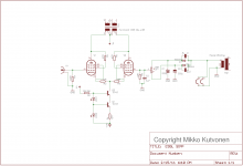
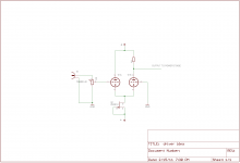
I'm balancing the power stage using a pot with it's wiper on the second powertube's unused grid. Or that's the idea. I have a schema of an E55L SIPP I whipped up for a friend to clarify the idea a bit. I'll try posting it later.
I have to admit that I've no idea how to calculate those additional windings on the power tranny. The idea isn't bad, though (why didn't I think of it myself..?). But how should I do this?
I'm actually a little bit tempted to using a preamp schematic as the driver. I've got this ECC99-based compound preamplifier (common cathode -> common anode) with both stages CCS loaded. The second tubes grid is directly coupled to the first tubes anode. About 5mA current per half. Measured 56 Vpp out at 0,9% THD including the distortion of the signal generator (-45 dB H2). Bandwidth was up to 450kHz and the resulting slew rate in the 160 V/µS range (I calculated a theoretical 175 V/µS before I measured, so I hit close enough to the mark...). Square waves were perfect at 20 Vpp and 150kHz. I've a perversion towards stupendously fast amplifiers. But this thing doesn't have enough gain (~20).
But how would just a simple 6SL7 common cathode design for example with a SS CCS load sound? Would there really be any advantage in using a SRPP stage?
I'm also trying to take the whole design of this amplifier as a learning opportunity. I've never used octal small signal tubes, I've never heard a SIPP, I've never used a tube rectifier. So I'm going to do all of these now.
Here's the schematic I had whipped up previously for my friend. Basically the idea is going to be quite the same with the 6V6's, but of course the OPT primaries would be totally different. Also the negative -12 volt supply would not be needed. The E55L biases at some -4 V on the grid in this arrangement (if I remember correctly), so the CCS at the tail needs some negative voltage to operate.
This circuit was designed to give a couple of watts in triode push pull, driven from a preamplifier. If someone wants to build this, tell me how it sounds. Though the schematic might have some bugs, I only had a coffee break's time for this.
This circuit was designed to give a couple of watts in triode push pull, driven from a preamplifier. If someone wants to build this, tell me how it sounds. Though the schematic might have some bugs, I only had a coffee break's time for this.
Attachments
Check this theme, discussed a while ago. Could also be made with a triode strapped pentode and a pentode.
- Status
- This old topic is closed. If you want to reopen this topic, contact a moderator using the "Report Post" button.
- Home
- Amplifiers
- Tubes / Valves
- Suggestions on SIPP driver stage