Ok, I am getting 50-70mV of 60Hz hum on the output of the input stage, none of the other stages seem to add any hum.
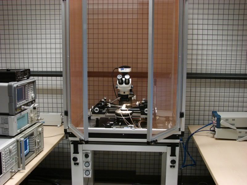
Hehe yeah the isolation table is great .... but the two pumps for it are super noisy.
Look at the filament supply wiring and have you applied the dc bias I suggested to the filament supply?
I have the heater circuit referenced to the cathode of KT88. Remember there is no 60Hz being created on the output of the 2nd 6SN7, just the first.
BTW. I am pretty convinced now that after I get this all working I will convert it back to the first schematic.
I've done the same trick and as long as there is no significant audio present it works just fine.
Now you need to go back and do some additional trouble shooting. The tube is sufficiently far from the power transformers that magnetic pick up is unlikely to be the culprit. My first suspicion would be a ground loop, and my next induction from the filament wiring. (Or - horrors, a terrible wiring error..
 I've done it with such consequences..) You haven't got more than one point grounded to the chassis do you? RCA jacks are either the only point connected to chassis or they are on isolation washers returned to the single common ground point - can't have both.
Yes I would go for fixed bias! And all component values as specified in the original design. Once it is working if you feel so inclined you can look for "improvements" or not.
Keep plugging away you are making real progress. Victory is at hand..
Last edited:
Yeah I have made progress for today. I think I will call it a day. I think I am going to put the hum thing down for now and figure out the NFB thing. I think I am applying PFB atm.... but that will wait for tomorrow. I am just happy you guys helped me solve the parasitic oscillation problem. Now I just have to solve new oscillation
Yes, I am pretty set on going back to the original schematic. I just want to solve the NFB/PFB thing and maybe the 60Hz hum before I take it apart.
This project had been a major undertaking for me, it was my first power amp and first tube project and I think i went alittle overboard. After doing this I have learned a lot and the 2nd monoblock will be MUCH improved.
This project had been a major undertaking for me, it was my first power amp and first tube project and I think i went alittle overboard. After doing this I have learned a lot and the 2nd monoblock will be MUCH improved.
... that's a major drawback of stereo: you have to do it again.
I may need to build an 8 channel buffer if I go to a digital x-over for my active speakers. Not looking forward to it.

Too true. My last project was a voltage reference (noise floor is something aorund -150dB, the gear we have here cannot actually measure any lower). Measured the first prototype channel and felt I was done ..... until i remembered i had to build 3 more channels.
An externally hosted image should be here but it was not working when we last tested it.
Very cool. I have designed references and VI (voltage/current source) for ATE applications with similar performance. Very difficult to measure, but as part of design validation you have to.. Another life away from audio..
Ok I just checked and I am about 99% sure I am applying PFB. I have checked the wiring about 100x and am pretty sure it matches the schematic. So can someone verify this for me.
Input stage = first inversion
Phase splitter = 2nd inversion
3rd gain stage = 3rd inversion
Output stage = 4th inversion
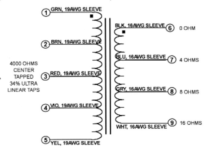
So the input signal and the feedback signal should be in-phase. Since the feedback signal is applied to the cathode will result in NFB. But i just measured the input signal and the feedback signal, and they are inverted ! Can someone confirm if the output stage is actually inverting (I am not 100% on OPTs) ?
Here is the OPT (showing dot convention)
Input stage = first inversion
Phase splitter = 2nd inversion
3rd gain stage = 3rd inversion
Output stage = 4th inversion
So the input signal and the feedback signal should be in-phase. Since the feedback signal is applied to the cathode will result in NFB. But i just measured the input signal and the feedback signal, and they are inverted ! Can someone confirm if the output stage is actually inverting (I am not 100% on OPTs) ?
Here is the OPT (showing dot convention)
Attachments
See post # 16, you have confirmed that the input and feedback are out of phase - all you need to do is swap either the connections to the grids of the output tubes or if it is tidier swap 1 & 5 and 2 & 4 on the primary. Since three of the stages are differential your convention is not necessarily correct and any one of the differential stages can be flipped in phase by swapping the input or output connections, but NOT both. Simplest might be to swap the transformer primary. Your call, but do it only in one (any) of those three stages. (2nd - 4th)
Last edited:
Ok i just swapped 2 of the phases and now it works. There are still problems but I am making serious progress. The problems I can see now
- Hum ? Not so sure the problem is still there
- Very limited power, the waveform gets all screwy after I get to about 6W (Ill take some photos later tonight of whats happening.
- When i connect the ground lead of one of my scope probes in an attempt to measure other nodes in the circuit the output goes all screwy again.
On small signal it looks like the cutoff frequency is about 150KHz.
Progress.. Clearly one or more of the stages is clipping prematurely if you are only getting 6W output.
To reduce the confusion you should open the NFB loop and making sure that the secondary is loaded properly before taking a look at each stage in turn to determine which is clipping first. A check of the zero signal dc operating conditions of each stage is necessary first to assure that the operating points of each stage are as expected. You can remove intermediate tubes if necessary to help you figure out what is going on. Start with the first stage and work forward in the signal chain verifying each stage is OK before moving on to the next. That's about it.
Keep posting your progress and/or lack thereof..
Clearly one or more of the stages is clipping prematurely if you are only getting 6W output.To reduce the confusion you should open the NFB loop and making sure that the secondary is loaded properly before taking a look at each stage in turn to determine which is clipping first. A check of the zero signal dc operating conditions of each stage is necessary first to assure that the operating points of each stage are as expected. You can remove intermediate tubes if necessary to help you figure out what is going on. Start with the first stage and work forward in the signal chain verifying each stage is OK before moving on to the next. That's about it.
Keep posting your progress and/or lack thereof..
Ok, the amp isn't clipping, it has WAY more than enough swing. The problem is stability. The gain actually increases as you increase in frequency, even at 188Khz the gain is still increasing. Putting a square wave on the input confirms, she is wildly unstable. I understand stability and all that business, but what confuses me is the increase in gain at high frequency.
Ok, the amp isn't clipping, it has WAY more than enough swing. The problem is stability. The gain actually increases as you increase in frequency, even at 188Khz the gain is still increasing. Putting a square wave on the input confirms, she is wildly unstable. I understand stability and all that business, but what confuses me is the increase in gain at high frequency.
Well that is odd, but the technique is much the same except that you need to determine which stage is responsible for the rising frequency response with frequency. I suspect that still points to something amiss in output stage. I would pull the output tubes and determine that the rest of the amplifier stages are flat just to be sure. This is open loop right? Otherwise it points to incorrectly phased negative feedback connection or possibly swapped screen grids.
I think I have the parasitic oscillation problem solved. I now have the following issues
- It seems i am getting a lot of 60Hz on my input stages
- Not entirely sure I am applying NFB, might be PFB, i am not sure I have the proper inversions wired up properly
- Not sure about my bias currents. the KT88 are drawing 85mA each, which i was under the impression I was suppose to aim for 50mA.
P.S. I really appreciate all of your FAST responses and interest. As much as this is driving me nut I am starting to remember why i use to love DIY audio.
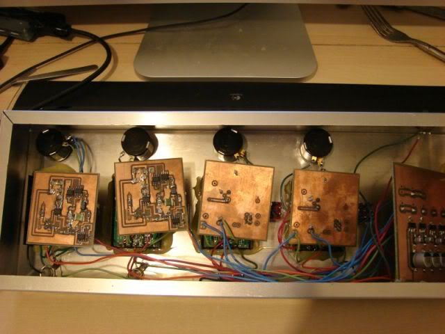
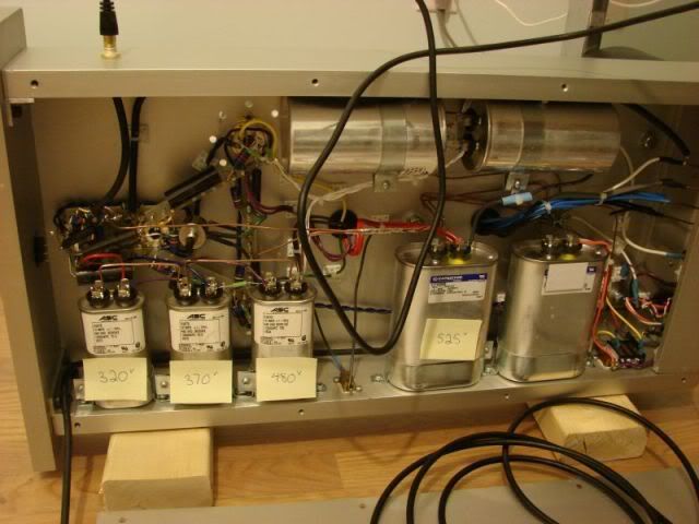
Ok here is the amp, please be gentile
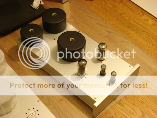
BTW Here is my day job (I am a doctrate student, so while I don't get paid I still call it a job).
Just curious after reading this thread. What kind of caps are those, the large metal cans? They look like motor starting or running caps.
Have you checked your UL connections yet? If they are reversed, it might explain things. I've got a potted OPT where one plate and UL tap were reversed in the potting process. I figured it out by measuring the DCR of the two wires in question in relation to the center tap.
- Status
- This old topic is closed. If you want to reopen this topic, contact a moderator using the "Report Post" button.
- Home
- Amplifiers
- Tubes / Valves
- Problem with my amp, and I have run out of ideas