The input impedance should be Rfb || Rg,
Yes, if the current sensing voltage were input to inverting input of the opamp.
But it is input to non-inverting input, so the input impedance is very high and not effected by Rfb and Rg. Look your schematic and you see my point.
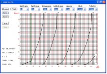
Here is the Triode Connected plot with Va and Ia limited so you can see the 0ma axis better.
I think if anything my Vos is such that it has shifted the plot down and I need to bias mine opposite what you did.
I still don't see how to force the "Imeasure" value to get the bias point where I want it. Int his plot where I wanted to see it biased at 1mA and 150V it went off the left of the 0V grid line where it would require positive grid voltage to get to 1mA of current.
Attachments
Last edited:
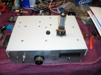
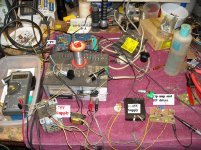
Here is what my test set looks like at this point. The chassis looked a lot bigger before I started assembling it.
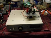
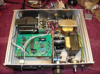
First pix is with a fixed adapter for the 6P1P, second shot is the configurable adapter, and the third shot is the underside.
The adapters plug into an octal socket.
The configurable adapter looks like it should oscillate, but the old Tektronix curve tracers got by with it so I figure it beats making a new adapter for every pin out.
The meter is not hooked up yet, but when finished will display filament/heater voltage or G2 Voltage. Heater supply is selectable 6.3/12.6 with a triac control to adjust the voltage. (yea, I need to clean it up and put a heat sink on the TRIAC.)
G2 supply is now variable from 10 to 400V. The fuse to the left of the adapter socket is for the G2 supply.
Attachments
I've been working on my design again. I have an 89C51 running with a couple of D/A converters on a prototype board. It is driving a small board with the level translator for drive the grid. I've got it set for about -64V max, although it would be simple to change it to 0-128V by simply changing the power supply and adjusting the gain.
Code is done for 0-511V for the anode drive (511 steps), and 0-32 steps for the grid drive. Two channels of D/A (12 bit) and four channels of A/D (10 bit) update in 150us per grid step, with 511 anode steps per grid step.
Next I'll test the anode drive(although it is the same as the grid except it uses N-FETs instead of P-FETs) to generate positive drive vs negative for the grid so I'm sure it will work.
It is a bit noisy as it is on breadboard.
Once I have the anode drive tested I'll start working on the computer interface. Probably in Visual C++, although I've been told the learning curve is a bit steep compared to Visual Basic.
This will probably end up a long term project.
HV anode drive works.
I guess the hardware feasibility study can be considered a success. So much for the easy part.
Attachments
Last edited:
I've been working on my design again. I have an 89C51 running with a couple of D/A converters on a prototype board. It is driving a small board with the level translator for drive the grid. I've got it set for about -64V max, although it would be simple to change it to 0-128V by simply changing the power supply and adjusting the gain.
Code is done for 0-511V for the anode drive (511 steps), and 0-32 steps for the grid drive. Two channels of D/A (12 bit) and four channels of A/D (10 bit) update in 150us per grid step, with 511 anode steps per grid step.
Next I'll test the anode drive(although it is the same as the grid except it uses N-FETs instead of P-FETs) to generate positive drive vs negative for the grid so I'm sure it will work.
It is a bit noisy as it is on breadboard.
Once I have the anode drive tested I'll start working on the computer interface. Probably in Visual C++, although I've been told the learning curve is a bit steep compared to Visual Basic.
This will probably end up a long term project.
HV anode drive works.
I guess the hardware feasibility study can be considered a success. So much for the easy part.
Hi,
Any further progress on this? Still looking back at my basic analogue curve tracer and wondering whether make sense to work around it a bit. Perhaps a simple ramp oscillator driving a MOSFET follower to feed the grid for transfer curve plotting?
Also a step generator like you originally proposed with a ramp oscillator for the anode voltage? Any thoughts as to how come up with a simple design?
Hope things are ok at your end,
Cheers
Ale
This is more of an exercise for me, as I've ordered the MODULE LAMPEMETRE ANALYSEUR - VACUUM TUBE ANALYZER.
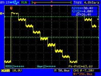
I added an SOA (Safe Operating Area) limiter to control the anode supply as I don't see any other practical way to protect the tubes from excessive dissipation at low grid voltages.
The plot shows grid steps in green and anode voltage in blue with the SOA limit in red.
If anyone sees any errors or oversights, please speak up.
Power dissipation dictates all the output FETs have heat sinks.
As is the drivers will need to be on heat sinks as well. However I think the load resistors of the drivers can be increased and made large enough to allow them to run without heat sinks. The changes may require tweaking other components.
Hi there,
is there any chance of sending me the ltspice circuit as I want to play around this?
Thanks
Ale
I sent the latest file plus the asy and sub files.
Hi Steven, thanks!
I did reply to your email, did you get mine?
Cheers,
Ale
Bump...
Any update on the board? I like to get one too...
Jaz
Has anyone solved the issue of the 10ohm resistors. I also purchased the board and preparing to fix it up.
Any update on the board? I like to get one too...
Jaz
- Status
- This old topic is closed. If you want to reopen this topic, contact a moderator using the "Report Post" button.
- Home
- Design & Build
- Equipment & Tools
- Valve testing machine