Hello, I would like to know your comments regarding 6J7 tube as 300B driver. I have studied the WE91 classic circuit to build my first SE amplifier and got some help from you too recently.
As a first try I will stay on a pentode driver like the WE amp. I have some 6J7 samples (GE) and also 6SJ7, which is a later similar valve. 310A tube is very difficult to obtain for me, and the suggested subs are 6J7, 6SJ7 and even 6C6 which was used in the early WE theater amp. Later will think in other driver possibilities but for now I like the WE pentode idea as a first try.
Some points:
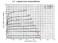
1- the image below shows GE plate curves. I have drawn 90K DC load line, which is the typical driver operating point for some WE91 based amplifiers including SP Joe Roberts adaptation with 370V B+. Understand that those resistors are for 310A. 6J7 is a bit different regarding max current, anode voltage, etc.
So I have drawn another line with lower load (around 50K). My concern is Miller effect on bandwith, so a lower Ra would help but my limit seems to be in the max current capability and max dissipation available with 6J7 (red dotted line).
Do you think from a purely theoretical point of view that 50K will work better?
2- Grid bias remains around -3 volt and on AC I still have more than +/-70 volts output, enough to make 300B work.
6J7 anode resistance in triode mode is 11K aprox. Using this value I calculated SG resistance around 55K:
rsg= ra(triode) x (Ia+Isg) / Isg
This value is important to design the SG voltage divider used in the classic circuit. Correct me If I’m wrong. Classic WE91 circuit uses 75K upper resistor and 30K lower resistor in voltage divider. To calculate voltage divider (B+ 420V) for desired SG DC voltage (around 100V) I should considered lower resistor in parallel with SG resistance.
I have discrepancies here. If SG draws about 0,5 mA at 100V, rsg is about 200K, not 55K // 30K. What is wrong with my reasoning?
Sorry for so lengthy post But I think could be usefull for other members too.
Best regards
As a first try I will stay on a pentode driver like the WE amp. I have some 6J7 samples (GE) and also 6SJ7, which is a later similar valve. 310A tube is very difficult to obtain for me, and the suggested subs are 6J7, 6SJ7 and even 6C6 which was used in the early WE theater amp. Later will think in other driver possibilities but for now I like the WE pentode idea as a first try.
Some points:
1- the image below shows GE plate curves. I have drawn 90K DC load line, which is the typical driver operating point for some WE91 based amplifiers including SP Joe Roberts adaptation with 370V B+. Understand that those resistors are for 310A. 6J7 is a bit different regarding max current, anode voltage, etc.
So I have drawn another line with lower load (around 50K). My concern is Miller effect on bandwith, so a lower Ra would help but my limit seems to be in the max current capability and max dissipation available with 6J7 (red dotted line).
Do you think from a purely theoretical point of view that 50K will work better?
2- Grid bias remains around -3 volt and on AC I still have more than +/-70 volts output, enough to make 300B work.
6J7 anode resistance in triode mode is 11K aprox. Using this value I calculated SG resistance around 55K:
rsg= ra(triode) x (Ia+Isg) / Isg
This value is important to design the SG voltage divider used in the classic circuit. Correct me If I’m wrong. Classic WE91 circuit uses 75K upper resistor and 30K lower resistor in voltage divider. To calculate voltage divider (B+ 420V) for desired SG DC voltage (around 100V) I should considered lower resistor in parallel with SG resistance.
I have discrepancies here. If SG draws about 0,5 mA at 100V, rsg is about 200K, not 55K // 30K. What is wrong with my reasoning?
Sorry for so lengthy post But I think could be usefull for other members too.
Best regards
Attachments
Hello, I would like to know your comments regarding 6J7 tube as 300B driver.
I would advise to forget about that. The 6J7 (6SJ7) is a small signal type. Its current sourcing capability is quite limited. The problem here is that the 300B will be too difficult of a load for the 6J7. Complaints about disappointing sonic performance from 300Bs are quite frequently due to inadequate grid drive.
Use the 6J7, but also include either a MOSFET source follower (best) or a stiff cathode follower grid driver. If going the MOSFET route, look for MOSFETs that can handle the voltage, and which have the lowest reverse transfer capacitance, as Crt becomes the major contributor to input capacitance. 6J7s, like all small signal VTs, like Hi-Z, Lo-C loads. The grid of a 300B is neither.
Do you think from a purely theoretical point of view that 50K will work better?
In this case you can not have the g1 voltage at - 3 V. This will cause higly distorted output from 6J7. Instead the g1 voltage should be around -2 volts.
But why don't you try a 6AC7 (or soviet 6J4) as a driver. It is essentially more steady tube for this purpose. It also has the same nice metal-look.
The problem here is that the 300B will be too difficult of a load for the 6J7.
As far as 300B will not be driven to grid curren - which is obviously the case now since a pentode tube is used as a driver - the load 300B forms is it's input- + Miller capacitance ( 70 pF) shunted with 390 kohms.
This is actually a very typical load, not difficult by any means.
In case the output resistance of the driver tube is 50 kohms, the high frequency cut-off is about 45 kHz.
As far as 300B will not be driven to grid curren - which is obviously the case now since a pentode tube is used as a driver - the load 300B forms is it's input- + Miller capacitance ( 70 pF) shunted with 390 kohms.
You're forgetting that DHTs, especially, have a nasty habit of pulling grid current even before Vgk actually goes positive. You still need a stiffer grid driver to supply that current demand.
I say again: almost all the complaints about disappointing sonic performance with 300B designs goes back to inadequate grid drive.
Thanks Prowler and Artosalo, read your advices with great interest.
Regarding the grid voltage I mentioned -3V as in the datasheet, but was aware that it was a little lower and many space is over the -3V line. With a need of +/- 1volt AC aprox. you are right -2V would be better, leaving some headroom to be away of 0V.
Checked 6AC7 data. Only concern is about heater voltage which they suggest to be DC not AC probably to avoid excesive noise/hum with greater gain.
Best regards
You're forgetting that DHTs, especially, have a nasty habit of pulling grid current even before Vgk actually goes positive.
At what grid voltage level you mean the grid current begins in 300B ?
Checked 6AC7 data. Only concern is about heater voltage which they suggest to be DC not AC probably to avoid excesive noise/hum with greater gain.
The manufacturer does not recommend 6AC7 - with AC heater - for low-level audio applications.
Your application is line level, which is actually quite high level as an input for a pentode tube.
I see that the difference between the level you mean and what the tube manufacturer means is some 30...40 dB.
So this should not be a problem at all.
Thorsten Loesch built a 300B amp using a pentode driver - in his case a 6BQ5/SV83 was used. Eventually that driver was swapped over to a C3m.
http://www.fortunecity.com/rivendell/xentar/1179/projects/legacy/Legacy.html
I build the SV83 version and got very good performance.
Loesch also had some thoughts on driving the 300B here: http://www.fortunecity.com/rivendell/xentar/1179/theory/seamptheory/SEAmplifiertheory.html
"In addition, a directly heated triode (and any similar triode) has a quite substantial Input Capacitance comprising mostly the milleramplified Anode to Grid Capacitance. The input Capacitance of a given Valve is (Cga + Cstray) * Mu + Cgk. This capacitance must be driven from somewhere, not only with respect to the frequency response, but also concerning the current draw at higher frequencies. For a 300B V`alve the input capacitance is usually around 70pF, a little more in reality due to stray capacitance's from the wiring or pcb. If we take 80pF Input Capacitance and a Bias of 70V for our above mentioned operating point we must be able to supply the current drawn by this capacitance up to at least 100kHz (usually a much higher frequency is strongly advisable) at full voltage swing. The impedance of the 80pF Capacitance at 100kHz is around 20kOhm, the peak current drawn by this capacitance at full signal is 3.5mA."
Last edited:
The impedance of the 80pF Capacitance at 100kHz is around 20kOhm, the peak current drawn by this capacitance at full signal is 3.5mA."
I really can not understand what does this has to do with HIFI-audio amplifier. Typical audio spectrum does not contain such frequencies around 100 kHz which will reach the full 70 V peak voltage level, I think not even at 10 kHz.
At what grid voltage level you mean the grid current begins in 300B ?
Dunnow, since I haven't done any designs for the 300B. (Audiophool expensive, faddish, boutique VT, whereas my design philosophy matches that of Fred Nachbaur: "As one type becomes expensive, we'll use something else -- because we can")
For the 845, for example, grid current becomes a problem somewhere north of Vgk= -5.0V. The originators of the type simply said t'hellwiddit, and placed in the spec sheet the suggestion that the input signal be limited such that Vgk= -5.0V was never exceeded. Although back in the mid-1930s, they did not have available power MOSFETs that can make source followers capable of slapping those 845 control grids silly. By taking Vgk all the way to zero volts, and providing grid current drive, you can get an extra couple of watts from an 845. That way, you just might be able to actually have a 20W SET, since the extra couple of watts might compensate for core/copper losses (at least partially) in the OPT.
I really can not understand what does this has to do with HIFI-audio amplifier. Typical audio spectrum does not contain such frequencies around 100 kHz which will reach the full 70 V peak voltage level, I think not even at 10 kHz.
Kstagger might be overdesigning just a bit, especially if you're not using gNFB. However, you will improve the sonic performance by reducing slew limiting as much as possible. And that means having a decent grid driver, either a source follower, a cathode follower made from a type that can pass decent current, or a power type like the 6BQ5 mentioned elsewhere here.
Weak grid driver + 300B= Sonic disappointment.
For the 845, for example, grid current becomes a problem somewhere north of Vgk= -5.0V.
If this is the case, then it is a surprise to me. I am aware that below -1 V grid current starts to flow, but below -5 V sounds strange.
Have to study this more.
- Status
- This old topic is closed. If you want to reopen this topic, contact a moderator using the "Report Post" button.
- Home
- Amplifiers
- Tubes / Valves
- 6J7 driver in WE91 like amplifier