First,
I am finishing up the design of my "new" system. I have come to some "sticking points" as to overall design and need some info/advice on how I should proceed.
The source I plan to use most (90%) of the time is a Behringer FCA-202 Firewire Interface using low latency ASIO drivers on a PC.
This interface can output either balanced or unbalanced.
Because of limitations using ASIO on a PC, I will have no "Master Volume" control at the source. (anyone using a PC as a source and ASIO will understand) but in a nutshell, some applications can control volume with ASIO but windows itself does not, so...if your using the "system" as your PC speakers you end up with all kinds of crazy levels and ideally you really do not want anything between the source digital material and the outputs.
I also plan to sometimes us vinyl and broadcast radio as sources.
Here are my dilemmas,
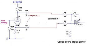
Immediately following the source(s) I plan to use a 2-way 24db/Octave LR active Xover using Opamps. The lows going to SS amps and subs.
The Hipass will then be split again @ about 2.5khz via a Pete Millet design all tube Xover. Those outputs going to PP 807 "Williamson" amps for biamping.
So the main issue is this, Ideally I would like to use "balanced" inputs into the SS Xover, the PCB has provisions for this and since the source might be a good ways away from the amps physically it makes sense.
BUT,
1. How to attenuate a balanced source easily using pots?
2. Most of the tube RIAA preamps designs I see are SE without Balanced outputs, so with the Xover built for balanced in's how to "balance" the outputs of the phono preamp and the other possible sources? (I would rather stay away from $$$$ trannies on the preamp.
Could I just use a rather low RP triode in a "split load" phase inverter layout with rather large coupling caps to prevent a low end roll off?
Attached is possible configuration, still need to know how to attenuate that level.
I am finishing up the design of my "new" system. I have come to some "sticking points" as to overall design and need some info/advice on how I should proceed.
The source I plan to use most (90%) of the time is a Behringer FCA-202 Firewire Interface using low latency ASIO drivers on a PC.
This interface can output either balanced or unbalanced.
Because of limitations using ASIO on a PC, I will have no "Master Volume" control at the source. (anyone using a PC as a source and ASIO will understand) but in a nutshell, some applications can control volume with ASIO but windows itself does not, so...if your using the "system" as your PC speakers you end up with all kinds of crazy levels and ideally you really do not want anything between the source digital material and the outputs.
I also plan to sometimes us vinyl and broadcast radio as sources.
Here are my dilemmas,
Immediately following the source(s) I plan to use a 2-way 24db/Octave LR active Xover using Opamps. The lows going to SS amps and subs.
The Hipass will then be split again @ about 2.5khz via a Pete Millet design all tube Xover. Those outputs going to PP 807 "Williamson" amps for biamping.
So the main issue is this, Ideally I would like to use "balanced" inputs into the SS Xover, the PCB has provisions for this and since the source might be a good ways away from the amps physically it makes sense.
BUT,
1. How to attenuate a balanced source easily using pots?
2. Most of the tube RIAA preamps designs I see are SE without Balanced outputs, so with the Xover built for balanced in's how to "balance" the outputs of the phono preamp and the other possible sources? (I would rather stay away from $$$$ trannies on the preamp.
Could I just use a rather low RP triode in a "split load" phase inverter layout with rather large coupling caps to prevent a low end roll off?
Attached is possible configuration, still need to know how to attenuate that level.
Attachments
I can't help any more, as I would not start from where you are!
DF96,
Where would you start? I am always glad to have outside suggestions. What exactly to you take issue with?
That phase-splitter you show does not produce a balanced interface. While the tube stage shows matching resistors connected to the plate and the cathode, the net impedance at the plate and cathode terminals will be very different. Yes, the signal will be differential in phase, but not balanced in impedance - Which is what defines a balanced interface. If you are truly after the noise cancelling benefits of a balanced interface, then transformers (sorry) at both ends is about optimal.
Since your diagram shows, however, that you plan to convert the differential signal back to single-ended at the far side of the interface, another effective, but inexpensive option is to use a single-ended (tube or otherwise) output stage instead of the phase-splitter to drive one phase of the differential line. Then, at the near side, connect the oppositely phased line to ground via a passive RCL network whose impedance matches that of the driven phase.
For example, if you have some single-ended tube gain stage featuring a 15K ohm output resistance driving the positive-phase leg of the interface through a 10uF A.C. Coupling cap., then you would connect the negative-phase leg through a 15K resistor and 10uF cap. wired in series to ground.
It's just that my system is much simpler. Sources (all unbalanced), switch/pot box (i.e. 'passive preamp'), valve amp, speakers. That's all. I prefer simplicity.
Ironically, two years ago the "plan" was a more simplistic version. If I could get to where I want to go that simply trust me I would.
For example, if you have some single-ended tube gain stage featuring a 15K ohm output resistance driving the positive-phase leg of the interface through a 10uF A.C. Coupling cap., then you would connect the negative-phase leg through a 15K resistor and 10uF cap. wired in series to ground.
Ken this sounds like a solution!!
Let me get this straight.
Assuming a proper switch gear I can run XLR jacks with my balanced signal to the inputs of the buffer as shown from my soundcard.
Then I can "switch in" the "unbalanced" input of the other sources to the Positive phase input and then couple the negative phase thru the same value cap and output resistance.
My question is are we taking output RESISTANCE ie; the resistor from junction of the coupling cap and output to ground or Zout Output IMPEDANCE of that stage?
Ken, as long as the loads are balanced (VERY important!), the impedances are balanced. The only nonideality is the difference in power supply rejection at the plate versus cathode. See my article in the first issue of Linear Audio for experimental verification.
The circuit as drawn, however, is severely flawed and will have high distortion. The grid needs to be referenced to a voltage approximately 1/3 of B+.
The circuit as drawn, however, is severely flawed and will have high distortion. The grid needs to be referenced to a voltage approximately 1/3 of B+.
Ken, as long as the loads are balanced (VERY important!), the impedances are balanced. The only nonideality is the difference in power supply rejection at the plate versus cathode. See my article in the first issue of Linear Audio for experimental verification.
The circuit as drawn, however, is severely flawed and will have high distortion. The grid needs to be referenced to a voltage approximately 1/3 of B+.
SY,
You are right!! It was an oversight on my part, I mean't to reference it to the cathode !!! 0 Volts bias for 10mA Current. It would have like 90 volts bias referenced to ground!!!
It was just a thrown together circuit to show my intent would not have been built like that.
I assume it would work the same if the driving stage was a cathode follower? Since it will be at the tail end of a phono stage I will have a very QUIET (hopefully) B+ source.
That phase-splitter you show does not produce a balanced interface. While the tube stage shows matching resistors connected to the plate and the cathode, the net impedance at the plate and cathode terminals will be very different. Yes, the signal will be differential in phase, but not balanced in impedance - Which is what defines a balanced interface. If you are truly after the noise cancelling benefits of a balanced interface, then transformers (sorry) at both ends is about optimal.
Balanced impedance entirely possible in single ended Cathodyne.
1/2 Mu follower at emitter , 1/2 Schade follower at collector.
Both ends having voltage gain of about 50 with 12AX7 triode.
Results almost same as long tail pair except: No cancellation of
the 2nd harmonic, no need for negative rail, triode operates on
its own CCS slope rather than sharing current vs another triode.
When plate and cathode voltage feedback have equal influence,
you will observe the "tail" swings 1/2 the input. Just like a LTP.
Notice the ratio of R2/R1 = Mu required for impedance match.
Sorry, direct coupled cathode feedback requires P Sand to flip
the phase. Anything N here just wouldn't have worked... There
aren't a great many choices in P. MJE350 may work (300V 20W)
if you can't find MJE15035 (350V 60W TO220).
The other Ken
Attachments
Last edited:
Ken this sounds like a solution!!
Let me get this straight.
Assuming a proper switch gear I can run XLR jacks with my balanced signal to the inputs of the buffer as shown from my soundcard.
Then I can "switch in" the "unbalanced" input of the other sources to the Positive phase input and then couple the negative phase thru the same value cap and output resistance.
My question is are we taking output RESISTANCE ie; the resistor from junction of the coupling cap and output to ground or Zout Output IMPEDANCE of that stage?
1) Yes.
2) We're talking about the net source (Zout) resistance - well, yes, the impedance, to be technically optimal, but that may greatly complicate the design of the matching RCL network. The more exact the matching, the better the noise-rejection will be. To a first order, however, you should get fairly good results by simply taking the Zout as a pure resistance - assuming that the driver stage's actual Zout is minimally reactive. The dominant Zout reactive element should then be the A.C. output coupling cap.
BTW, this technique is presented in the signal transformer book written by Bill Whitlock of Jensen Transformers.
Ken, as long as the loads are balanced (VERY important!), the impedances are balanced. The only nonideality is the difference in power supply rejection at the plate versus cathode. See my article in the first issue of Linear Audio for experimental verification.
The circuit as drawn, however, is severely flawed and will have high distortion. The grid needs to be referenced to a voltage approximately 1/3 of B+.
Hi Sy,
I thought that I seemed to recall there maybe being some controversy regarding the balanced impedance presented by concertina phase-splitter. Something about the strictly series current path inherently creating a dynamic impedance match at both the plate and cathode. Interesting, that your experiment would appear to confirm that.
-Ken
I thought the grid reference for maximum headroom would be at (1/4)B+ ?
If another triode's plate were direct coupled in at such low voltage, it may
have trouble at the lower end of the swing. Is this why you say (1/3)B+ ?
See Post #10, input at ground level and plate at 250V, both probs solved.
If another triode's plate were direct coupled in at such low voltage, it may
have trouble at the lower end of the swing. Is this why you say (1/3)B+ ?
See Post #10, input at ground level and plate at 250V, both probs solved.
1/4 (if N) or 3/4 (if P) so output voltages can swing from rails to 1/2.
There might have to be concessions for devices that won't operate
properly when starved of voltage. I'm not sure what fraction of B+
is optimal for conventional triode driving triode? Front end with plate
swing from B+/2 to 0 centered at 1/4 obviously going to have issues
with grid leak when the plate voltage swings low. 1/3 might even be
the correct bias for triode driving triode, definitely not saying it isn't.
The full range is no problem for Triode driving P sand.
Plate never sees less than B+/2.
Attachments
Last edited:
Equal Z split also possible with 6SN7 at 300V into 10K loads (per post #1)
Going back to single ended, you might look into Broskie Cathode Follower
http://www.tubecad.com/october99/page10.html
Going back to single ended, you might look into Broskie Cathode Follower
http://www.tubecad.com/october99/page10.html
Attachments
Last edited:
Broskie Cathode Follower
It seems to me that the Broskie C.F. is EXACTLY the circuit I am looking for!!.
In essence it replicates a transformer input for the balanced output of the sound card.
Broskie's articles are a little lacking in detail (or at least I can't gleen the answers to my questions from it) So if anyone can help with the following questions.
In the attached pic from Broskie's article what is the effect of the 50K resistors from input to grid and grid to anode output?
Also, I assume the 1M at the output is to not "swamp out" the input impedance of the next stage?
I guess what I am asking is this, which components set the input impedance that the preceding stage "sees" and what would be an appropriate value given an output impedance of ~1K from the preceding stage?
Attachments
Consider first the top two 50K resistors. The left one acts as a grid stopper. The right one provides grid bias, and is bootstrapped by the upper valve acting as a cathode follower.
Now the lower two 50K. They are the input and feedback resistors for an anode follower using the lower valve. The 1M at the output provides grid bias for the lower valve, and fixes the DC output potential at 0V.
Consider a balanced voltage signal applied to the input. The + signal will appear unchanged at the output (via upper CF). The - signal will be cancelled at the lower grid by feedback action, so the lower valve will do nothing. The impedance seen at the + input will be high, because it is 50K in series with a bootstrapped 50K (plus 1M in parallel). The impedance at the - input will be 50K, as it is 50K to a virtual earth at the lower grid. So this is not a balanced input, as the impedances differ.
A common-mode voltage applied to both inputs will, I think, result in zero output. Each valve will see half the input voltage at their grid-cathode, so they will pull the output in opposite directions. Each input will see 100K impedance, so total is 50K.
- Status
- This old topic is closed. If you want to reopen this topic, contact a moderator using the "Report Post" button.
- Home
- Amplifiers
- Tubes / Valves
- balanced/unbalanced questions decision time