Being a complete novice with little or no understanding of circuits means I am a bit at a loss here.
If I pull the cover will each of the components have detail on them that will tell me what they are? I could do that and then write them down if that would help in understanding the circuitry better?
It does sound like this could be improved significantly but would the suggestions be in the realm of a complete novice to undertake?
Proceed with caution. Take a pen or pencil and poke around, but please make sure to use one hand while doing so and give the amp about a day of being unplugged to start digging around. Those capacitors can hold charge after the power has been disconnected.
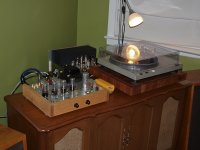
That hum sure sounds like it could be either a grounding issue or bad filtering. I am not impressed with the whole design. It does look like someone could have done a better job with the design details and neatness.
Morgan Jones - 633 pages
He is funny though; I think I'm going to enjoy this read.
I so want to make something out of this POS!
Suggestions welcomed.
Read a little at time, it will go faster than you think... I find it compelling reading, but then again I am a Geek..

UPDATE:
So I didn't get a chance to do anything with this and actually just stuck it in a cupboard. I recently got a Magnavox 185 modified amp and have been using that with the Vista phono stage.
Anyway, I decided to try introducing the Chinese preamp into the equation and lo and behold: no hum! Not only no hum but increased bass and just more 'balls'. So for now, until I can get a knowledgeable 'friend of a friend' to take a look at the preamp, it's staying.
I have been paying close attention to all the tubes on both amp and preamp to check for additional heat or brighter glow as an indication of something being overloaded but all seems well so far.
I appreciate all the helpful input and will post again once I have had a professional give it the once over.
Attachments
If the two coupling caps coming off the splitter tube (2nd) are flipped on the schematic, then the phasing is corrected for the negative feedback. So likely just a drawing error on the schematic. The top (3rd) tube has bootstrapping of its load resistor by the output to equalize the output tube gains. Assuming the other power caps are really 450 V (150 V a typo), and the other questionable part values are just typos, then it looks like it should be working fine. (But it does DEFINITELY need some safety discharge resistors added across the power supply caps.) Just a way overly complex design for a line-amp. One might consider putting some small output transformers on the thing to make it into a low power stereo speaker amp, since its 90% of the way there already.
Last edited:
Thanks Stereo-amp, I appreciate the continued input. I think the consensus was that the schematic was not the correct one and of course my attempt at filing in the details didn't add much! In its current state are you suggesting that it could possibly be dangerous (not having the safety discharge resistors) as I would pull it out of the system if that is the case?
I hadn't considered it as an amp but given that it is almost there as you say then maybe that will be its next evolution.
Watch this space
I hadn't considered it as an amp but given that it is almost there as you say then maybe that will be its next evolution.
Watch this space
So a year and a half later, after one failed attempt to have the preamp checked over I finally had someone from Audiokarma give it the once over. He fixed up some soldering issues and replaced a few dying capacitors. He also sketched a circuit diagram for me which I wanted to post here for feedback and thoughts about possible improvements.
Attachments
- Status
- This old topic is closed. If you want to reopen this topic, contact a moderator using the "Report Post" button.
- Home
- Amplifiers
- Tubes / Valves
- What's wrong with this?