Sorry..yes, I meant D4 (and D5 now that you mention it)
If you want plug-n-play low maint then cathode bias is fine. Fixed bias allows you to adjust the output tube bias as the tubes wear over time, and also allows a little more power for a given B+ since the cathode is essentially grounded instead of sitting at the voltage at the top of the cathode R (more drop across the tube for a given B+).
Fixed bias requires a negative rail, and some R's and a couple of adjusting pots. You have the winding, so I figured I'd throw it out there.
Fixed bias also requires a lower value grid leak R as well.
Last edited:
I appreciate the suggestion, boywonder.
Simply the amp's going to someone who mentioned low maintenance as being preferred, so I thought about it for a bit then decided against it. If it was my own amp, I would not afraid of taking the multimeter out every once in a while to adjust bias, but it's not the case here...
Simply the amp's going to someone who mentioned low maintenance as being preferred, so I thought about it for a bit then decided against it. If it was my own amp, I would not afraid of taking the multimeter out every once in a while to adjust bias, but it's not the case here...
Turns out it was an administrator account issue. the program is working fine, but I'd appreciate some advice:
I'm putting C1=110uF and R1=330R based on my schematic, but I'm getting pretty unclear about the load I should put, nor am I really sure about the source resistance. Any advice? I might be missing something really obvious, it happens.
SI
I'm putting C1=110uF and R1=330R based on my schematic, but I'm getting pretty unclear about the load I should put, nor am I really sure about the source resistance. Any advice? I might be missing something really obvious, it happens.
SI
Turns out it was an administrator account issue. the program is working fine, but I'd appreciate some advice:
I'm putting C1=110uF and R1=330R based on my schematic, but I'm getting pretty unclear about the load I should put, nor am I really sure about the source resistance. Any advice? I might be missing something really obvious, it happens.
SI
Sounds like you are getting it.
Change the resistive load to constant current and pop in a couple of current taps where appropriate for the various B+ values. Input the current draw for each tap in the schematic.
Leave the source resistance of the transformer as-is to start, once you get the schema correct, hit "simulate" then select V(I1), V(I2), etc to display the voltages at the various current taps.
If you click on the transformer properties box, you'll see three dots in the drop down window, they allow you to input various transformer source R's, etc. If you don't have the transformer yet, just leave the default source R in there to start.
I'm getting a pretty impressive number of different failure messages, and getting kind of scared...
Here's a screenshot of the whole window. please let me know what I should be looking for/ what I should do next:
https://lh5.googleusercontent.com/-801lgbvAeDk/TXE3fDL7HsI/AAAAAAAAAS0/rdtl9vq-Vm8/s1600/8512281.jpg
Thanks!
SI
Here's a screenshot of the whole window. please let me know what I should be looking for/ what I should do next:
https://lh5.googleusercontent.com/-801lgbvAeDk/TXE3fDL7HsI/AAAAAAAAAS0/rdtl9vq-Vm8/s1600/8512281.jpg
Thanks!
SI
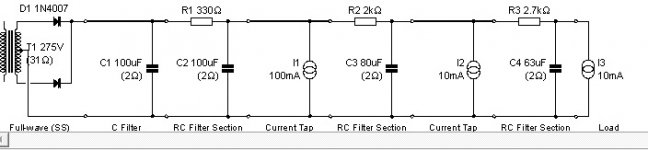
Your PSUD schematic should look like this:
Notice the current taps I1, I2, and I3. Add those just like adding RC stages. I guessed on the current draw for each tap so you will need to dial that in a bit. Changing the current draw at each tap will change the voltages......my guesses are close....
I1 is your output tube draw, I2 is your phase splitter current, and I3 is your preamp current.
Get this up and modeled, then we can look at your error messages.
Attachments
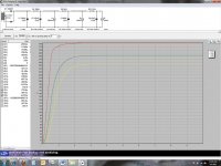
Here are some results after a bit of experimentation. I get a "current sink pulled V below zero for more than 5 main cycles" note, other than that, all of these B+ values are close to what I needed. The final tap is a DC bias for the heaters, wired to the wiper of the humdinger.
Thoughts?
Thoughts?
Attachments
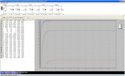
Looks fine....
Check your ripple voltage by mouse clicking a window around a small portion of the flat part of each B+ voltage. You will have to mouse click a window several times as you'll want to zoom way in. You can see how flat (or wavy ) the wave form is.
Keep in mind that PP stages can tolerate more ripple V than SE stages...
Use the zoom out magnifier on the upper right to zoom out, allowing you to zoom in by mouse clicking for the highest voltage (you can't zoom in on the highest voltage without zooming out first. Then try increasing the value of C2 and see what it does to the ripple V. Also note less ripple V for each subsequent stage, as expected.
Another way of checking ripple is to put in a reporting delay (to the right of the simulate box) so that the voltages are fully up before being plotted, then just read the min and max data fields for each voltage.
Also check for ringing by stepping the currents after say 5 seconds in the current drop down window.
Check your ripple voltage by mouse clicking a window around a small portion of the flat part of each B+ voltage. You will have to mouse click a window several times as you'll want to zoom way in. You can see how flat (or wavy
) the wave form is. Keep in mind that PP stages can tolerate more ripple V than SE stages...
Use the zoom out magnifier on the upper right to zoom out, allowing you to zoom in by mouse clicking for the highest voltage (you can't zoom in on the highest voltage without zooming out first. Then try increasing the value of C2 and see what it does to the ripple V. Also note less ripple V for each subsequent stage, as expected.
Another way of checking ripple is to put in a reporting delay (to the right of the simulate box) so that the voltages are fully up before being plotted, then just read the min and max data fields for each voltage.
Also check for ringing by stepping the currents after say 5 seconds in the current drop down window.
I get less than 1V of ripple on the first current tap, then less then .5 on the second. After that it's pretty unnoticeable (screenshots to come soon) for a C2 of 150uF. I think this is more than good enough, right?
I'm currently experimenting with current step downs. What are reasonable steps to expect, and should I be looking at anything in particular here? I'm assuming the different high output voltages, like earlier, but just making sure. Screenshots to come soon for that as well.
I'm currently experimenting with current step downs. What are reasonable steps to expect, and should I be looking at anything in particular here? I'm assuming the different high output voltages, like earlier, but just making sure. Screenshots to come soon for that as well.
Latest simulation screenshot viewable at bottom of the following page: Elephant Space Snowstorm: Electronics
Thanks for your thoughts,
SI
Thanks for your thoughts,
SI
- Status
- This old topic is closed. If you want to reopen this topic, contact a moderator using the "Report Post" button.
- Home
- Amplifiers
- Tubes / Valves
- HiFi Tube amp project