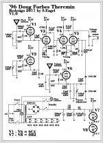
I'm considering building a tube theremin. I was checking several popular schematics an decided I'm going with Doug Forbes '95 design with some adjustments here and there.
Here's the original scheme -
Forbes wrote a text explaining the project and that's great because it makes everything easier and I've found out that several people built his design and it sounded good. It's also quite easy project compared to RCA , Keepinger and several others.
Here's another page containing the text and some additional notes:
Vacuum Tube Theremin
I'm going to use 6C4 tubes instead of 12AU7 (cheaper) and I want a different PS probably with two 0B2's and no choke (I just happen to have no choke available and I have a dozen of 0B2's). I will draw the scheme and post it later.
My main question is about coils. I'm going to wire the coils myself, with all the oscillator coils having 66:33 turns (according to the notes from the page above). But there's one unexplained coil with the volume adjustment capacitor over it. It's right to the left from the volume antenna coil (which is 33:66) and has no tap. What is it? How many turns should it have???
The other question is about small capacitors over the coils. The pitch antenna coil has 150pF and 33pF in parallel. Why is that? Is that some special tuning arrangement? Looks like the author simply added 33pF to the 150pF and it worked better. Should I put one 180pF instead? And then the mysterious no-tap coil has 15pF+22pF. What is this? Parallel? Series?
The cathode resistor for V3 is not labelled. Doug writes that it is 10K (???), or is it just an option?
I'm posting the original Doug Forbes' text here, since his webpage is dead and the other page I've found the text at may die too, who knows.
A Tube-Type Theremin Construction Project.
When RCA introduced their version of Lev Termen's invention they
said it was as easy to play as humming. While the sound that can
be produced by the Theremin may at times sound like singing or
like a violin, the fact that you don't touch it to play it
removes the tactile feedback normally found in the playing of a
musical instrument. The musician stands motionless except the
slight movement of the hands, closer to the pitch antenna and the
notes glide up scale, further away and lower tones are produced.
The closer the hand is to the volume antenna, the louder the
sound. (this is the reverse of the original instrument, but I
find it more intuitive to play this way.)Of the many Theremins
that I have built the ones based on tubes sound the best and have
the most sensitivity to the players' hand positions. The design
presented here is the culmination of many years of
experimentation.
The Theremin works on the principle that if you add two radio
frequency signals together in a nonlinear amplifier the resulting
output will be the sum and the difference of the input
frequencies. In the Theremin we want the pitch antenna to control
one frequency and the other one to be fixed. As the performers'
hand adds capacitance to the tuned circuit controlling the
variable frequency, the difference between the two becomes
greater, resulting in an audible tone. The same "detuning"
principle controls the volume.
The pitch antenna is connected to a parallel resonant circuit
that forms a Hartly oscillator operating at about 7OOkHz. I chose
the operating frequency to be high enough so that the half a
pico-farad that the hand represents would provide a sufficiently
large change in frequency and so alignment could be done using a
AM radio. The fixed-frequency is provided by the Hartly
oscillator around Va. The 150pf variable capacitor is mounted on
the front panel and is the pitch control. It is adjusted so that
when the performer is furthest away there is no audible tone but
as the hand is brought forward the pitch rises. Another design
criterion was that the Theremin be capable of playing very low
notes. There is a tendency for the oscillators to lock onto one
another when their frequencies are close. This causes the lowest
note to be the one right before lock, usually a few hundred
hertz. By using separate tubes for the two oscillators and by
preventing any coupling between them the unit can produce tones
down to tens of hertz. The RF signals are added and subtracted in
the mixer tube V2b. By changing the value of the lk resistor in
the cathode line, the tube can be operated in a more nonlinear
manner which along with the 10k resistor in the cathodes of V3
can alter the sound of the Theremin dramatically. The sum of the
RF signals is not wanted and can cause background noises so it is
bypassed to ground by the lonf cap in V3a's grid. V3a and b are
used as a voltage controlled amplifier in which the audio is
applied to the grid of V3a and the control voltage to the grid of
V3b. V4a is an oscillator just like the pitch ones except that
the operating frequency is different. If the frequencies were
close there would be hetrodyning (sum and differencing) between
these stages resulting in extra notes that would not follow the
pitch antenna. The output of the volume oscillator is connected
to a parallel resonant circuit that shunts the RF signal to
ground when the oscillator frequency is above or below the
circuits center frequency. When the two frequencies match,
maximum voltage is presented to the voltage doubler consisting of
the two diodes. As a result the grid of V3b is less negative and
maximum output is achieved at the plate of V3a. The 150pf
capacitor that controls the volume oscillator is mounted on the
front panel and is adjusted for minimum volume when the performer
is furthest away. As can be seen the circuit is Class-A, single-
ended-triode throughout. The power supply is a straightforward,
zener shunt-regulated type and any combination of components
resulting in a regulated supply of approximately 250 volts DC
would work as well.
As far as construction notes are concerned; keep the wires short,
I used point-to-point wiring in my unit, and place the pitch and
volume oscillators as far away from one another as possible. The
volume antenna on my unit is a piece of PC board material about
8" by 4" mounted parallel to the floor and on the left-hand side
of the Theremin. The pitch antenna is mounted vertically and is a
telescoping antenna from a portable radio. My Theremin was
designed around inexpensive coils available from Antique
Electronics (PC-70-OS $3.00) and the other parts should be
available in a well-stocked junk box. Silver Mica or NPO caps in
the tuned circuit are a nice addition to keep the unit from
drifting to much, but the player compensates for the drift
anyway. Alignment of the unit is most easily done with an
oscilloscope or a frequency counter or both, but the 7OOkHz range
was chosen so that an AM radio could be used to align the
Theremin. Start by removing Vl and V4, this will leave V2 as the
only operating oscillator. Adjust the pitch capacitor on the
front panel to the halfway position, tune the radio to about
7OOkHz and bring it near L2. Tune the radio and the pitch
capacitor until a hiss is heard that can be moved along the radio
dial with the pitch cap. Plug Vl in and repeat the above
procedure using the slug in Ll and the radio dial. When you get
both hisses on the radio adjust the slugs in Ll and L2 so that
they occur at the same place on the radio dial. When they are
close, a squeal will be heard on the radio and if you can't wait,
you can start playing the instrument right now. Replace V4 and
connect the Theremin to an amplifier line input. The squeal on
the radio should now be coming out of the amp. Adjust the volume
capacitor on the front panel to the halfway position and
alternately adjust L3 and L4 until a point can be found where
minimum volume occurs.
There are a few areas to explore now that you have a working
model. First how about a second fixed-pitch oscillator for a
second note say a fifth up. Second you might try wiring another
parallel resonant circuit in series with the pitch and volume
antenna wires to increase the sensitivity even further.
All of the Theremin articles I have read caution the would-be
Thereminist to practice for quite a while before attempting the
"premier performance" and after hearing Clara Rockmore (The Art
of the Theremin, Delos CD) I totally agree. I use the instrument
with a bunch of synthesizers and stick to more experimental kinds
of music. Some really great, although non-traditional, Theremin
sounds can be obtained by running the output through signal
processors such as frequency dividers, Echo, and distortion
units. Rave On.
Good insight into building a Forbes Theremin here, seems to go into some detail about caps and coils
Welcome to the MR Theremin Web site!
Welcome to the MR Theremin Web site!
MR
Thanks for the link, I've got through the page and it answered a question about the unlabeled cathode resistor, but the rest, and mostly important - the mysterious coil one - are not answered. I'm afraid it's just dumb me not understandig something obvious. This coil is probably the second wiring of the volume antenna coil, but they do not appear to be the same coil, so I'm confused.
Thanks for the link, I've got through the page and it answered a question about the unlabeled cathode resistor, but the rest, and mostly important - the mysterious coil one - are not answered. I'm afraid it's just dumb me not understandig something obvious. This coil is probably the second wiring of the volume antenna coil, but they do not appear to be the same coil, so I'm confused.
Hi, the circuit around your unknown coil, the two 1N4148 diodes, and the 10nF capacitor near the grid of V3b, is known as a "slope detector." It converts the frequency output of the volume oscillator to a DC voltage. It works as follows. The coil and parallel caps form an LC resonant circuit. Suppose it is tuned to the frequency of the volume oscillator when the player's hand is at infinity. The detector formed by the two diodes and the 10nF capacitor now gives a maximum output. If the player's hand approaches the volume antenna, the oscillator shifts and its frequency moves away from the resonant frequency of said LC circuit. Since the Q of this LC circuit is not infinite (due to the inductor's DCR, etc.), the impedance of the LC circuit drops gradually (hence the name slope) as the volume oscillator's frequency shifts. As a result, the detector will output a different voltage.
You can play around with adding resistance to the LC circuit, lowering Q, resulting in a different hand distance vs. volume transfer function.
Regarding the tail resistor R3, it has to be dimensioned properly for the anode voltage and tube type you'll be using. Lookup the website of the "Valve wizard," he has a chapter there which explains how to calculate this resistor (look under "long tail pair" phase splitter).
Hope this helps.
Kenneth
slopes
thank you, kavermei!
I'm learning the slope detectors now, but I' still far from understanding the interaction of all these coils. looks like the unlabelled coil should be wired on the same core as the volume antenna coil and in order to be tuned to volume coil frequency it should be like 100 turns (volume coil = 33+66).
I'm happy to say that at least I understand the cathode resistor story.
Hi engels,
no you must not wind the two coils on the same core, as that would create a feedback or feedforward loop from the output of the oscillator to its input. This is not what we want. On the contrary the coils should be at right angles from each other to minimize coupling.
The coils do not need to be the same value, but the natural frequency of the slope detector LC circuit should equal to that of the oscillator LC circuit. In your particular schematic, the detector C value is larger so the coil could be made smaller than the oscillator coil.
BTW. Instead of the slope detector LC circuit, you can also buy a ready-made, three-legged, 455kHz ceramic filter. Or you could take a 455kHz IF tuned circuit from a defective radio. They are the small metal boxes with a tuning screw at the top. If you use one of these then you only need to make sure that the volume oscillator works at roughly this frequency (by changing the oscillator coil or by adding capacitance, and using a frequency counter or a multimeter with a frequency range).
Kenneth
Will cathode coupled oscillators not care the slight
difference in Miller?
I don't know if they do, but in any case it's not really a problem. The pitch section works by detecting the frequency difference between two oscillators, so if they both shift a bit in frequency, it is of no consequence for the frequency difference.
Regarding the volume osc, this needs to be tweaked anyway for each build depending on stray capacitance etc. so again I wouldn't worry about it.
Kenneth
Silly cheap pitch Theremin, no volume control that I can see.
Dude performing the demo video almost knows what he's doing.
Sand state, but well worth the quick look.
Gakken Otona no Kagaku vol. 17 ~ Science Projects for Adults -- Theremin mini
Dude performing the demo video almost knows what he's doing.
Sand state, but well worth the quick look.
Gakken Otona no Kagaku vol. 17 ~ Science Projects for Adults -- Theremin mini
- Status
- This old topic is closed. If you want to reopen this topic, contact a moderator using the "Report Post" button.
- Home
- Live Sound
- Instruments and Amps
- Theremin project needs some help!