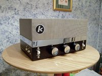
I pulled this from somebody's trash on the side of the road, it was mounted in what looks like an early 50's radio frame. Im not 100% if this is the right model, I found a similar looking knight here: Knight KG-240 stereo amplifier Radio Allied Radio Corp.;
to my surprise it worked when I plugged it in and applied a signal to the phono input.
it worked for about... 3 hrs, later the next day I was playing some music through it when the audio slowly faded away... I turned up the volume pot hoping it was a rough section on the pot but the audio stayed very low and scratchy. When I switch the inputs and flip the input switch it only outputs a little bit of scratchy audio on the phono input.
My buddy suggested I replace the filter cap, but after an hr of googling the internet, this is probably not the problem since there is no 60hz hum.
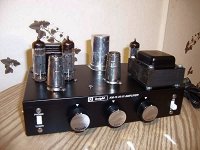
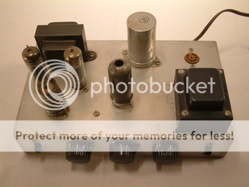
Here are the tubes that it has in it:
the 2 tubes with metal shields over them are: ECC83/12AX7
2 tubes side by side: EL84/6B05
one tube all by itself over by the filter capacitor: all i can read is EX80
any assistance is greatly appreciated since I have no idea how this amp even works lol.
as for my workshop, I have access to pretty much anything you can think of: DMM, scopes, leakage/capacitance measurement tools etc
thanks in advance!
here are some pics I took:
and here is a video of the actual amp and its symptoms:
YouTube - knight amplifier broken
to my surprise it worked when I plugged it in and applied a signal to the phono input.
it worked for about... 3 hrs, later the next day I was playing some music through it when the audio slowly faded away... I turned up the volume pot hoping it was a rough section on the pot but the audio stayed very low and scratchy. When I switch the inputs and flip the input switch it only outputs a little bit of scratchy audio on the phono input.
My buddy suggested I replace the filter cap, but after an hr of googling the internet, this is probably not the problem since there is no 60hz hum.
Here are the tubes that it has in it:
the 2 tubes with metal shields over them are: ECC83/12AX7
2 tubes side by side: EL84/6B05
one tube all by itself over by the filter capacitor: all i can read is EX80
any assistance is greatly appreciated since I have no idea how this amp even works lol.
as for my workshop, I have access to pretty much anything you can think of: DMM, scopes, leakage/capacitance measurement tools etc
thanks in advance!
here are some pics I took:
An externally hosted image should be here but it was not working when we last tested it.
An externally hosted image should be here but it was not working when we last tested it.
An externally hosted image should be here but it was not working when we last tested it.
and here is a video of the actual amp and its symptoms:
YouTube - knight amplifier broken
Nice find! The 'EX80' is probably an EZ80 by the looks of it, which is a rectifier.
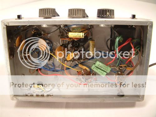
Well, a good place to start is by drawing a schematic (or finding one online). Then perform some DC measurements as well as AC ones (scope). At first glance, the underside of the chassis looks really good; all I can see is that there are these two components (they look like high voltage, small value caps) that are obviously fried. Those will have to be replaced in any case, but before doing so, try to analyze this amp a bit further.
Well, a good place to start is by drawing a schematic (or finding one online). Then perform some DC measurements as well as AC ones (scope). At first glance, the underside of the chassis looks really good; all I can see is that there are these two components (they look like high voltage, small value caps) that are obviously fried. Those will have to be replaced in any case, but before doing so, try to analyze this amp a bit further.
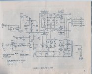
Look here:
MANUAL+SCHEMATIC KNIGHT 83Y784 Tube Amplifier 83 Y 784 - eBay (item 120593078200 end time Feb-02-11 07:16:07 PST)
It appears to be the original manual for your amp!
I bet you need some tubes, a couple caps (at minimum) and some switch/pot cleaning.
MANUAL+SCHEMATIC KNIGHT 83Y784 Tube Amplifier 83 Y 784 - eBay (item 120593078200 end time Feb-02-11 07:16:07 PST)
It appears to be the original manual for your amp!
I bet you need some tubes, a couple caps (at minimum) and some switch/pot cleaning.
A Sweetie
I got one for Christmas in 1967 when I was 12. Mine was a 12 Watt Knight Kit KM-15. I sold mine in 1972. I missed it and was delighted to find these pictures of one online. My gripe about that unit was it's small output transformer, as the amp is power bandwidth rated 30-15,000 hz, +/- 3db and will only do 6 watts at 30 hz. A pair of those with heavy output transformers would be really sweet!
Yours looks like an older version of that model, but the circuit is probably identical to the Knight Kit KM-15 and you might find such a manual on ebay or somewhere else online.
Attachments
Last edited:
Hi hvguy1,
Welcome to the forum.
The phono socket isn't going to sound very good if your playing something else other than vinyl through it, stick to the tuner socket, operate your switch a few times just in case there is a build up of corrosion.
Those EL84's usually have about 300v dc on their anodes so be careful, recommend you read the sticky thread on safety if you havn't already done so!

ps try swapping the ECC83/12AX7's around.
Welcome to the forum.
The phono socket isn't going to sound very good if your playing something else other than vinyl through it, stick to the tuner socket, operate your switch a few times just in case there is a build up of corrosion.
Those EL84's usually have about 300v dc on their anodes so be careful, recommend you read the sticky thread on safety if you havn't already done so!
ps try swapping the ECC83/12AX7's around.
Last edited:
My buddy suggested I replace the filter cap, but after an hr of googling the internet, this is probably not the problem since there is no 60hz hum.
This sounds like good advice to me - at least in the long run. If it doesn't leak now it will in the future. The absence of a hum through the speakers doesn't necessarily mean (imho) that your filter cap isn't leaking. If it is then maybe not enough B+ voltage will reach the valves. This would be my first check with the meter if nothing more obvious showed up on inspection.
Also on the safety issue, I can't see an earth cable - is there one?
Brgds Bill
its like Christmas with all these valuable responses!
im going to replace the obvious wax caps with .02uf 600v caps. then run it.. if no good, then ill switch tubes around.
thanks again for all the responses!
Keep in mind that if a filter cap is bad it could take out the rectifier - and you can't diagnose the rectifier tube by switching it around.
It is possible that the filter cap (metal can on the top in the back) is leaking. After it got warm the leakage increased causing an increased drain on the rectifier tube leading to a slowly decreasisng B+ voltage and the sound fading away. As stated this can (and might have) kill the rectifier tube. Continued operation can lead to a fried power transformer and even an exploding cap.
If the can cap got warm during the initial testing this is surely the case. It the plates (the large black metal parts) inside the rectifier tube glowed red the cap is probably dead.
If the can cap got warm during the initial testing this is surely the case. It the plates (the large black metal parts) inside the rectifier tube glowed red the cap is probably dead.
I operated the switch about 40 times, its in good shape, replaced the caps that were obviously in bad shape... however when I tested them, the rating on the cap was .22@600v, they measured .2456@600v. I replaced them anyway =)The phono socket isn't going to sound very good if your playing something else other than vinyl through it, stick to the tuner socket, operate your switch a few times just in case there is a build up of corrosion.
Those EL84's usually have about 300v dc on their anodes so be careful, recommend you read the sticky thread on safety if you havn't already done so!
ps try swapping the ECC83/12AX7's around.
poked around for loose solder joints and swapped the 12ax7's around and still no luck, still scratchy.
on what tube should I measure what? and are measurements taken from ground?
thanks again!
thanks for the schematic, im probing around on the pre-amp and notice the bias resistors are WAY out of tolerance,This amp is a Knight-Kit KM-15 HI-FI amp. It's just one of 10 billion 6BQ5 push-pull monoblocks, but its great for free.
after replacing the resistors I noticed the bias voltage on pin 1 of the 12ax7 is 125v and the bias on pin 6 is 75v. does this sound correct?
however when I replaced all the broken parts there became no output, not even a crackle
hmmm
trash can amp
I suggest leaving the pre-amp alone for now (you could even take the tube out of the amp). Plug the "line out" of a CD player into the "tuner" input and get the main amp working. Once thats done, go back and clean up the pre-amp. Check to be sure the voltages are CLOSE to whats on the schematic, they will never be exact. If you have a scope, look for ripple in the power supply. Have fun.......
I suggest leaving the pre-amp alone for now (you could even take the tube out of the amp). Plug the "line out" of a CD player into the "tuner" input and get the main amp working. Once thats done, go back and clean up the pre-amp. Check to be sure the voltages are CLOSE to whats on the schematic, they will never be exact. If you have a scope, look for ripple in the power supply. Have fun.......
I suggest leaving the pre-amp alone for now (you could even take the tube out of the amp). Plug the "line out" of a CD player into the "tuner" input and get the main amp working. Once thats done, go back and clean up the pre-amp. Check to be sure the voltages are CLOSE to whats on the schematic, they will never be exact. If you have a scope, look for ripple in the power supply. Have fun.......
I noticed that the preamp was clipping the hell out of my input "supplied by a signal generator" i was thinking the input level was too high, but 1.4khz at 500mv is pretty low IMO, but replacing the resistors on the bias fixed that..
ill do some probing around later this evening.
trash can amp lol, nice
after replacing the resistors I noticed the bias voltage on pin 1 of the 12ax7 is 125v and the bias on pin 6 is 75v. does this sound correct?
In the preamp, IIRC pins 1 and 6 of the 12ax7 are the anodes. According to my reading of the schemo the anodes should both read +75v dc referenced to ground. Also it looks like there is a grid bias of -75v dc. Is it possible that the grid voltage has been added into your anode voltage to make up your measured voltage of 125v dc ie measured from the wrong side of R2 - just a thought.
In any case I agree with Brucetassin.
IMHO it would be a better bet to check the voltages coming off the four caps in the multican and not be sidelined by the preamp. It seems to me that the multican is providing anode voltages, screen voltages and even involved in providing the 12v cathode bias for the EL84's ( the 20ufd cap is bypassing the 220 ohm cathode resistor ) - I would want to make sure all is well here.
Brgds Bill
Last edited:
ie measured from the wrong side of R2
Correction - wrong side of R7 - apologies
ah, all fixed, thanks to my buddys help.
come to find out nearly half of the resistors were over 20% out of tolerances. But the main resistors that were messed up were the resistors R16 and 17 on the main amplifier section "top right of the schemo. Resistors 3 and 6 were reading 280k lol, way outside of their 150k window. And as I noted in a previous post; i replaced c-14 and 15 since they were melted to death lol.
before I fixed it I snapped a pic of the waveform I was getting: blue is pin 1 on the pre-amp equalizer 12ax7 tube after I replaced the out-of-tolerance bias resistors and yellow is the output from the final stage of the amp where the speaker is hooked up.
video of the finished product is here:
YouTube - fixed knight tube amplifier KM-15
does anyone know what frame that radio is? I cant find its similar design anywhere...
come to find out nearly half of the resistors were over 20% out of tolerances. But the main resistors that were messed up were the resistors R16 and 17 on the main amplifier section "top right of the schemo. Resistors 3 and 6 were reading 280k lol, way outside of their 150k window. And as I noted in a previous post; i replaced c-14 and 15 since they were melted to death lol.
before I fixed it I snapped a pic of the waveform I was getting: blue is pin 1 on the pre-amp equalizer 12ax7 tube after I replaced the out-of-tolerance bias resistors and yellow is the output from the final stage of the amp where the speaker is hooked up.
An externally hosted image should be here but it was not working when we last tested it.
video of the finished product is here:
YouTube - fixed knight tube amplifier KM-15
does anyone know what frame that radio is? I cant find its similar design anywhere...
I just purchased (over the weekend) what appears to be either a home-made copy of the KM-15 or one that was placed in a home-made chassis. I'm still waiting it's arrival in the mail, but I have the photo's from ebay. One thing interesting to me is that the amp is coming from the Chicago area... the old home of allied from what I've read.
The underside components look to be virtually identical to the photo's I've seen online of the KM-15, and the top layout is almost the same (one 12ax7 is shifted) Also, the 12ax7 shields and the knobs are different.
I found this thread, and thought I'd add to it if people don't mind. I'm hoping to get some good advice as I go. Here are the photo's (from the ebay add) I'll take some better one's once I get the amp.
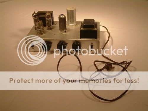
My goal is to turn this into a small guitar amp.
My 1st question as I'm very green with analog electronics especially tubes. Can I install the rectifier (I have one on order), remove all the other tubes, and check output volatges w/o damaging the rectifier? Or does there have to be some sort of load across it?
If this test passes, would I be safe to install all the tubes, connect a speaker, and see what it does? I'm not worried about the passive components, I just want to minimize the risk of damaging tubes or transformers.
Thanks,
Rick
The underside components look to be virtually identical to the photo's I've seen online of the KM-15, and the top layout is almost the same (one 12ax7 is shifted) Also, the 12ax7 shields and the knobs are different.
I found this thread, and thought I'd add to it if people don't mind. I'm hoping to get some good advice as I go. Here are the photo's (from the ebay add) I'll take some better one's once I get the amp.
My goal is to turn this into a small guitar amp.
My 1st question as I'm very green with analog electronics especially tubes. Can I install the rectifier (I have one on order), remove all the other tubes, and check output volatges w/o damaging the rectifier? Or does there have to be some sort of load across it?
If this test passes, would I be safe to install all the tubes, connect a speaker, and see what it does? I'm not worried about the passive components, I just want to minimize the risk of damaging tubes or transformers.
Thanks,
Rick
- Status
- This old topic is closed. If you want to reopen this topic, contact a moderator using the "Report Post" button.
- Home
- Amplifiers
- Tubes / Valves
- knight KG-240? low output help