In addition to what euro21 pointed out, the output transformer primary has very little inductance (10uH). Output transformers are used to match the high impedance of a tube with the low impedance of a speaker. Typically an output transformer will have between 10H and 60H.The link no longer works.
I have a schematic that uses a scavenged phonograph transformer, only know the resistances. I used the second method and getting no voltage out, is there a bug in the program? Did try different ratios and distances between, plus grounding various ways to no avail.
View attachment 1148291
Below you can see values for a Hammond 1628:
Attachments
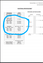
Try this parameters:
Transcendar_5k:8
L1 43H ; primary inductance
R1 381 ; primary resistance
L2 .055H ; secondary inductance
R2 .85 ; secondary resistance
K1 L1 L2 .99975 ; coupling coefficient
C1 5p ; primary side capacitance
C2 20p ; secondary side capacitance
C3 520p ; primary to secondary capacitance
Transcendar_5k:8
L1 43H ; primary inductance
R1 381 ; primary resistance
L2 .055H ; secondary inductance
R2 .85 ; secondary resistance
K1 L1 L2 .99975 ; coupling coefficient
C1 5p ; primary side capacitance
C2 20p ; secondary side capacitance
C3 520p ; primary to secondary capacitance
I said that is what did.Wrong. Primary (upper leg) tied to ground!!!
Connect it to B+.
I was falling the instructions.
Still does not work. Delete the program and re-install to git rid of the bug?In addition to what euro21 pointed out, the output transformer primary has very little inductance (10uH). Output transformers are used to match the high impedance of a tube with the low impedance of a speaker. Typically an output transformer will have between 10H and 60H.
Below you can see values for a Hammond 1628:
Interesting the instructions posted in this thread are so wrong, just goes to show not everything on here is accurate.
Thank you!Try this parameters:
Transcendar_5k:8
L1 43H ; primary inductance
R1 381 ; primary resistance
L2 .055H ; secondary inductance
R2 .85 ; secondary resistance
K1 L1 L2 .99975 ; coupling coefficient
C1 5p ; primary side capacitance
C2 20p ; secondary side capacitance
C3 520p ; primary to secondary capacitance
")
Still does not work... I was of the understanding generate a component, fine, treated it like a tube, though no generic transformer component so must mean use the inductor transformer method.
Attachments

What if a OPT is missing Rp2, no 16Ω tap (no Rs1), Rs2, and Rs3?
https://sklep.toroidy.pl/en_US/p/-T...nsformer-8kOhm-Cathode-Feedback-Push-pull/661
The other issue is getting a fatal error. No clue what this means...

https://sklep.toroidy.pl/en_US/p/-T...nsformer-8kOhm-Cathode-Feedback-Push-pull/661
The other issue is getting a fatal error. No clue what this means...
I have no clue what you just said... I do not see wires connecting L1 and L2, so how then are they coupled?
Oh! Thank you!Read post #4.
K is coupling coefficient between coils.
Spice directive: K L1 L2 0.99975
By the way, been fighting the model provided and not loading in the tetrode, gives an error message.
Do you have tetrode.asy?
If not, copy this to empty txt file and save as tetrode.asy.
Version 4
SymbolType CELL
LINE Normal -48 0 -48 16
LINE Normal 48 0 48 16
LINE Normal 0 -48 0 -16
LINE Normal -20 -16 20 -16
LINE Normal -20 -12 20 -12
LINE Normal -20 -16 -20 -12
LINE Normal 20 -16 20 -12
LINE Normal 48 0 28 0
LINE Normal 20 0 12 0
LINE Normal 4 0 -4 0
LINE Normal -12 0 -20 0
LINE Normal -28 0 -36 0
LINE Normal -48 16 -28 16
LINE Normal -20 16 -12 16
LINE Normal -4 16 4 16
LINE Normal 12 16 20 16
LINE Normal 28 16 36 16
LINE Normal -24 28 24 28
LINE Normal -32 64 -32 36
LINE Normal -24 28 -32 36
LINE Normal 24 28 32 36
LINE Normal -28 32 28 32
ARC Normal -48 -48 48 48 48 0 -48 0
ARC Normal -48 -32 48 64 -48 16 48 16
WINDOW 0 8 -64 Left 0
WINDOW 3 -24 80 Left 0
SYMATTR Value Tetrode
SYMATTR Prefix X
SYMATTR Description This symbol is for use with a subcircuit macromodel that you supply.
PIN 0 -48 NONE 0
PINATTR PinName Anode
PINATTR SpiceOrder 1
PIN 48 0 NONE 0
PINATTR PinName Screen
PINATTR SpiceOrder 2
PIN -48 16 NONE 0
PINATTR PinName Grid
PINATTR SpiceOrder 3
PIN -32 64 NONE 0
PINATTR PinName Cathode
PINATTR SpiceOrder 4
Neat!Do you have tetrode.asy?
If not, copy this to empty txt file and save as tetrode.asy.
Yes, I have it, just not a ECC81, only ECC83 (thought had used a ECC81 before...).ECC81..83 is triode, so need triode.asy as symbol, as you showed in #55 post.Neat!
Tetrode symbol represents four pin tube, as EL84.
Both requires.
sample:

I am not understanding what you are getting at... I just checked and it is using triode.asy.ECC81..83 is triode, so need triode.asy as symbol, as you showed in #55 post.
Tetrode symbol represents four pin tube, as EL84.
Checked the data sheet and says triode: https://frank.pocnet.net/sheets/010/e/ECC81.pdf.
Edit. Pasted in a known working ECC83, then got unhappy about the EL84, so pasted in a known working EL84, and now upset about the ECC83.
Edit 2. Just hit me while working on a different model yours had the scripts stripped when downloaded and loaded onto the PC. Bet that is it, going to try that.
Edit 3. Now it can't find the diode... I can't win.
Edit 4. I got it!
Found the .model text, scripted it in, and ran with no errors. Came out to 10 percent THD.
Last edited:
Well I am somewhat satisfied, it ran, however, with the ECC81, distortion went to 18 percent, plus the diode is getting 293V (not the 20V specified), something has corrupted in the file transfer. Glad have it, learned how to adapt a model for the architecture of my file setup and input a .model script (totally intuitive, no instructions needed).
Thank you, I forgot.Please attach asc file.
Attachments
- Home
- Amplifiers
- Tubes / Valves
- SPICE Transformer Model Spreadsheet