I have read and researched about DC heating my 300B SE amp.
What is the best practice to ground the cathode?
1. Same as the AC setup with each leg to a humpot and then to the 880 ohm resistor?
2. No humpot and one leg grounded through the cap and the other through the 880 ohm resistor?
3. Simply one leg to ground?
Others?
What is the best practice to ground the cathode?
1. Same as the AC setup with each leg to a humpot and then to the 880 ohm resistor?
2. No humpot and one leg grounded through the cap and the other through the 880 ohm resistor?
3. Simply one leg to ground?
Others?
Rod Coleman is selling a great little regulated supply board and components for very little. I am using them on the GM70 which can get VERY noisey even with hum pots. With the pure DC supply, it should be silent.
Here is a good thread about it. Go to the later pages.
http://www.diyaudio.com/forums/tubes-valves/38248-new-dht-heater.html
Here is a good thread about it. Go to the later pages.
http://www.diyaudio.com/forums/tubes-valves/38248-new-dht-heater.html
Last edited:
A single connexion for a cathode resistor is best. usually the Filament + terminal is a better choice than Filament -, but it is worth checking both, on a new design of 300B-SE.
When comparing dc heating solutions, there are a few things to watch out for:
- the filament voltage affects the cathode-to-anode voltage along the filament's length. This means that there is a potential gradient of signal (MUSIC!) voltage across the filament. Therefore, any heater solution that requires a capacitor across the filament (ie any dc voltage regulator) will force the signal through this capacitor (usually electrolytic). This will give distortion of its own. And, if the capacitor is less than about 47000 uF, there will be a LF-rolloff in this diverted current, too.
- The heater should buffer the anode current from the dc heater's raw dc supply, because of the rectifier noise, AND because the stray capacitance path causes anode-current leakage to safety-ground - exposing it to poor dielectrics, like PVC transformer leads, etc. and other noise sources.
- The feedback path of the heater-current should not be exposed to the anode-current. If this happens, the anode current transients may enter the feedback loop, and corrupt the dc heater current setting.
- the 3-terminal regulators are noisy, and perform badly in current-source mode. Using these will give a bad impression of what dc heating can do!
Best choices are the Tentlabs module for a ready-made solution, or very large chokes, or if you want a low-cost DIY kit, I have these available still.
http://www.diyaudio.com/forums/tubes-valves/38248-new-dht-heater-6.html#post2425121
All of these can operate without capacitors across the filament, and for LCL solutions, and my kits, and maybe Tentlabs too - the feedback loop is either absent or out of reach of the anode current.
Attachments
Never mind just answered my own question....
Here is what I did...I took vinylsavior's advice and simply connected H+ and H- to the tube socket. I took one of the legs to the bypassed cathode resistor. I am getting exacly 70V across both channels for a bias of 79.5mA.
The amp is much quieter now but there is still a little hum maybe 120hz...it used to be audible when in the room near the speakers. Now you have to get right up to them.
They are some homemade speakers based upon Zaph SR-71s ~91dB sensitivity.
Thanks for the guidance!
The amp is much quieter now but there is still a little hum maybe 120hz...it used to be audible when in the room near the speakers. Now you have to get right up to them.
I guess that's the best you can do with 91dB speakers.
djn, Rod, what supply voltage does your board need for push-push GM-70?
Kenneth
Hi!
I disagree. 91dB is not a very efficient speaker at all. With DC filaments it is possible to make a 300B amp absolutely quiet on a 91dB speaker, even with your ear right at the speaker.
Even on a 100dB speaker, a DHT amp can be made absolutely quiet.
I'd check the cause of the remaining buzz. It can be from the filament supply, or from insuffiecient filtering on the B+. Other causes are possible too, like coupling from the PSU, poor layout, especially ground wiring.
Best regards
Thomas
I guess that's the best you can do with 91dB speakers.
djn, Rod, what supply voltage does your board need for push-push GM-70?
Kenneth
Kenneth, can run the boards from 24.5V (min) up to about 29V with well chosen heatsink.
Dear all. How much ripple is ok for this setup? (DC heating 300b) I am a bit new here.
50mV, 10mV, 3mV, 20uV ?
Are there any right answer for this?
There is no straight answer. Depends on your circuit and speakers. When you don't get any hum which is disturbing it is ok. Just try and modify until you are happy.
Thomas
Dear all. How much ripple is ok for this setup? (DC heating 300b) I am a bit new here.
50mV, 10mV, 3mV, 20uV ?
Are there any right answer for this?
Thanks in advance.
About 10 mV /measured with AVO-metter/
- the filament voltage affects the cathode-to-anode voltage along the filament's length. This means that there is a potential gradient of signal (MUSIC!) voltage across the filament.
Rod,
I've seen this talked about in various threads but am confused a bit. Do you mean that the current through the filament is the sum of the filament current and the anode current with a high-z filament supply? I'm having trouble seeing how that could be true but I'm curious if that is really what you are trying to say.
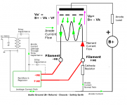
Let's say you have the filament connected up as per the drawing in post #6: Filament + is returned to system power supply [GND]. The Filament - [NEG] terminal is floating, so far as the B+ power supply is concerned.
The filament heating current drops 5V [for 300B] from Filament + to filament -, and this forces a difference in HT potential between Anode to F+ [say, 360V] and Anode to F- [355V]. Between F+ and F-, there's a dc resistance of about 4 ohms, for a 300B.
With this arrangement, the anode *current* will all flow through the F+ terminal, but due to the geometry of the filament [crossing the widest dimension of the internal aperture of the anode] some of the electron flow will be emitted from different portions of the filament's length.
The fraction of electrons emitted at some distance from the Filament + terminal will be replaced by electron current sourced from the filament + terminal [electron flow, rather than conventional current - which flows in the opposite direction]. Of course, this fraction of the anode current must travel along the filament to reach the site of its thermionic emission.
So, we end up with a distribution of current along the length of the filament, which is slight heavier at the filament + end, due to the forced difference in HT between the two filament terminals (forced by the filament heat voltage).
Even though the current travelling through the filament is not 100% of the anode current , it is still added to the anode current at the Filament + terminal. This is important, because noise and hum in the filament HEATING current will distort this part of the current flow, and degrade the sound.
Also, this illustrates the problem with ordinary dc heating [with a capacitor across the filament]:
- the capacitor must show a small, frequency-independent impedance compared the 4-ohm of the filament
- must not add distortion.
THe only candidates to achieve the first requirement (47000uF or higher, electrolytic) are unlikely to meet the second!
Hi!
In which environment? Audible hum will be extremely different with the same ripple say between a 93dB and 103dB speaker.
Resulting hum on the ouput will also depend on the winding ratio of your output transformer. There will be a 3dB difference on the hum level at the loudspeaker terminal with the same amout of ripple between a 2,5k and a 5k output transformer.
That means the requirements for the ripple can be 10-12dB or even more different between systems. Thats a facto of 4.
Best regards
Thomas
About 10 mV /measured with AVO-metter/
In which environment? Audible hum will be extremely different with the same ripple say between a 93dB and 103dB speaker.
Resulting hum on the ouput will also depend on the winding ratio of your output transformer. There will be a 3dB difference on the hum level at the loudspeaker terminal with the same amout of ripple between a 2,5k and a 5k output transformer.
That means the requirements for the ripple can be 10-12dB or even more different between systems. Thats a facto of 4.
Best regards
Thomas
With this arrangement, the anode *current* will all flow through the F+ terminal, but due to the geometry of the filament [crossing the widest dimension of the internal aperture of the anode] some of the electron flow will be emitted from different portions of the filament's length.
I was thinking that the emission per unit length of the filament would be pretty much constant. Naturally, electrons would tend to congregate on the most positive portion of the filament as that is where they find the weakest repulsive forces.
I've often wondered how strong this distribution shift is in reality since there is a grid in close proximity that sits tens of volts negative of the entire filament.
I guess my confusion was that people seemed to be saying that there is a current flowing in the filament when it seems to me that there is a current flowing in the space charge through the vacuum. I was having trouble balancing the currents.
I guess my next question is: is my initial assumption correct that emission is constant across the filament or does the space charge distribution affect the emission of the filament across its length?
Grid-to Cathode effective voltage will still vary from [say] 70V at one end, to 65V at the other, so I might expect a little difference, but the 300B has a large volume internal to the anode - this will give fairly gentle contours of E-field.
I don't think the emission will be wildly different across different portions of the filament, overall. This will still cause some of the current to flow within the filament's wire, I believe - the emission sites will be replenished from the filament core below.
I don't think the emission will be wildly different across different portions of the filament, overall. This will still cause some of the current to flow within the filament's wire, I believe - the emission sites will be replenished from the filament core below.
- Status
- This old topic is closed. If you want to reopen this topic, contact a moderator using the "Report Post" button.
- Home
- Amplifiers
- Tubes / Valves
- 300B DC heaters confusion