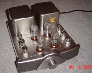
I have an Onix SP3 5881 P-P tube amp. Worked fine, then I decided to add some film caps to output caps on PS, and replace the coupling caps. Nothing major. When I powered it up one of the power tubes started glowing blue and then 15 seconds later started red plating. I checked the bias with the pots provided on the amp: the other 3 tubes were .30-.4v, the red plater was 10v(!) (the recommended is 1.15v setting for this amp). Swapping tubes didn't help. I took off the bypass caps on the PS and issues remains. The preamp, driver, phase and 3 other power tubes seem fine. Any ideas on troubleshooting?
I made no rearranging of components, just popped bypass caps on and then off so I'm at a loss.
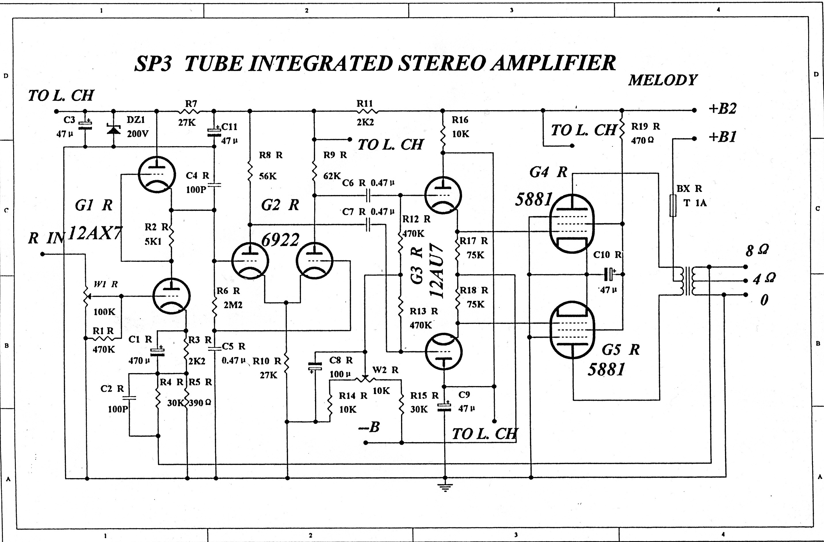
Here's the schematics from another thread:
I made no rearranging of components, just popped bypass caps on and then off so I'm at a loss.
Here's the schematics from another thread:
Attachments

Since this happened after your intervention, the most probable thing is that YOU make a mistake !
Are output tube still red when you remove the 12AU7 ?
If yes, hunt for a short that killed the -B supply.
If not, suspect your new link caps.
BTW they don't need to be so big
Yves.
Are output tube still red when you remove the 12AU7 ?
If yes, hunt for a short that killed the -B supply.
If not, suspect your new link caps.
BTW they don't need to be so big
Yves.
I hate to be the one to tell you this, but I'm afraid that what you've witnessed is what Tubelab calls the "Red Glow of Death".
According to this site, you appear to have an outdated version of the schematic:
The tube measuring 10 V is drawing 330 mA or so cathode current - causing a combined grid and plate dissipation of around 117 Watts!!! Depending on how long the tube was in that state, you'll be extremely lucky indeed if something hasn't melted inside, like grid wires and such. Even worse, drawing that kind of current through circuits not designed for it can easily blow expensive parts - like output transformers.
It's tough for me to go much further without knowing exactly what parts were replaced or bypassed, or without a revised schematic showing the actual bias circuit used.
According to this site, you appear to have an outdated version of the schematic:
Given this information I can only assume that the 30 Ω resistor is used for bias measurement. If this is indeed the case then the 0.3 to 0.4 V measurements on the other three tubes correspond to a cathode current of 10 to 13 mA, meaning that they're operating at near cutoff (total dissipation of around 3 to 4 Watts each).This circuit appears to be of an earlier version of the SP3 since it only shows one bias adjustment pot per channel, but we know that there are 2 pots/channel--one per output tube. So, they must have reconfigured the biasing circuit. to allow for biasing each output tube individually. The circuit was further modified so that the cathode of each output tube is now grounded via a 30 ohm resistor (in the diagram, the cathode is connected directly to ground).
The tube measuring 10 V is drawing 330 mA or so cathode current - causing a combined grid and plate dissipation of around 117 Watts!!!
Depending on how long the tube was in that state, you'll be extremely lucky indeed if something hasn't melted inside, like grid wires and such. Even worse, drawing that kind of current through circuits not designed for it can easily blow expensive parts - like output transformers.It's tough for me to go much further without knowing exactly what parts were replaced or bypassed, or without a revised schematic showing the actual bias circuit used.
Since this happened after your intervention, the most probable thing is that YOU make a mistake !
Are output tube still red when you remove the 12AU7 ?
If yes, hunt for a short that killed the -B supply.
If not, suspect your new link caps.
BTW they don't need to be so big
Yves.
I reflowed the solder on the PS joints where I had the bypass caps and also tightened down that socket - it was somewhat loose. No red plating so far, but some of the tubes do have some blue glow now which I don't recall previously. I will re-test tomorrow and proceed from there.
I hate to be the one to tell you this, but I'm afraid that what you've witnessed is what Tubelab calls the "Red Glow of Death".
According to this site, you appear to have an outdated version of the schematic:
Given this information I can only assume that the 30 Ω resistor is used for bias measurement. If this is indeed the case then the 0.3 to 0.4 V measurements on the other three tubes correspond to a cathode current of 10 to 13 mA, meaning that they're operating at near cutoff (total dissipation of around 3 to 4 Watts each).
The tube measuring 10 V is drawing 330 mA or so cathode current - causing a combined grid and plate dissipation of around 117 Watts!!!
It's tough for me to go much further without knowing exactly what parts were replaced or bypassed, or without a revised schematic showing the actual bias circuit used.
I only had the tube on for 15- 20 seconds at a time. Yes it was damn hot and i figured that tube was drawing a ridiculous amount of wattage, but luckily there seems to be no damage to the rest of the amp so far. Bias is now 2v on the problem socket and 1.3 on the other I tested. Off to bed before I do more.
Last edited:
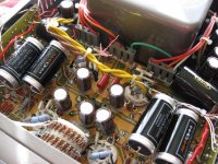
Those coupling caps really need some sleeving on their leads. With all those leads snaking around, they're just aching to short against something.
Yeah, I intend to do that though there's more room around them than it seems in the picture.
I assume the new coupling capacitors are much larger than the old ones. They will have much more stray capacitance to nearby circuit nodes. The result could be ultrasonic/RF oscillation around the phase splitter/driver stages, due to capacitive positive feedback. This may explain the blue - RF can do this to a valve. One option is simply to use normal good quality caps instead of giant boutique items. Another option is to see if you can insert a grounded insulated screen around the caps.
I had similar trouble with a 5-20 phase splitter, due to large coupling caps to the outputs. A screen made of a zigzag of stiff copper wire solved the problem. It stopped the input to the phase splitter from seeing the output.
I had similar trouble with a 5-20 phase splitter, due to large coupling caps to the outputs. A screen made of a zigzag of stiff copper wire solved the problem. It stopped the input to the phase splitter from seeing the output.
Those coupling caps really need some sleeving on their leads. With all those leads snaking around, they're just aching to short against something.
I would NOT power up this amp until this was taken care of. You are just asking for a destructive failure.
I would NOT power up this amp until this was taken care of. You are just asking for a destructive failure.
Guys I understand. The depth of field is flat in the picture so it seems more cramped than it is, no leads are touching
anything else. The oscillate = blue I will check out. I am not happy about the size either and will insulate leads, but they do not appear to be the issue.
Pics
The wires on many of those capacitors really appear (regardless of depth of field) to be touching their cases where they bend around the ends. The cases are metal and therefore conductive. I'd recommend teflon sleeves on all of them with a careful re-installation.
Last edited:
The wires on many of those capacitors really appear (regardless of depth of field) to be touching their cases where they bend around the ends. The cases are metal and therefore conductive. I'd recommend teflon sleeves on all of them with a careful re-installation.
I see what you're saying, I misunderstood what you guys were talking about. Yes I think some of the leads may have been touching the cans
. I thought the references were to leads touching other leads... Sometimes I miss the obvious.I see what you're saying, I misunderstood what you guys were talking about. Yes I think some of the leads may have been touching the cans
Happens to all of us, and I bet these leads are at the root of your issue. I suspect it will work just fine once you address this issue. Changing out the coupling caps is a simple upgrade I have found to be effective in a lot of budget and vintage amps.
if these caps are interstage caps and one wire (+) touches the can you will have a link and not a cap, that link will pass the voltage that is present at the anode of the preamp tube, ie. not good!
Other than the problem with excessive voltage at the output tubes grid it can also cause oscillations due to heavily changed operating point.
(and even cause oscillations thrue the feedbackloop if present.)
Other than the problem with excessive voltage at the output tubes grid it can also cause oscillations due to heavily changed operating point.
(and even cause oscillations thrue the feedbackloop if present.)
I put in some smaller caps and insulated the leads. Biasing is back to normal. So far so good. Thanks everyone.
great news!!
Actually, i was impressed by the building quality inside, it actually looks like a very high quality amp
great news!!
Actually, i was impressed by the building quality inside, it actually looks like a very high quality amp
Yeah, not bad for $500 (used)!
http://www.diyaudio.com/forums/atta...plating-help-onix-sp3-amplifier-schematic.jpg
6922 is a TP... What's the pentode section doing.. or is it incorrect tube number ?
richy
6922 is a TP... What's the pentode section doing.. or is it incorrect tube number ?
richy
- Status
- This old topic is closed. If you want to reopen this topic, contact a moderator using the "Report Post" button.
- Home
- Amplifiers
- Tubes / Valves
- Blue Tube Red Plating = Help!