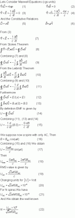
As a DIYer, all your work with a solder, (and all Classical Electrodynamics too) whith exception of Thermionic Effect and Semiconductor Theory (Quantum Mechanics), came from only four equations and two constitutive relationsand You must at least see them one time in your life. Eq.(1) to (4) are called Maxwell Equations due to his creator James Clerk Maxwell.
If You are afraid of Mathematical Physics, skip the Theory after take a look on Maxwell Eq.!-Mandatory-
Well, go to Transformers
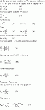
Eq.(51) is the well known
Np = (Upx10^8)/(√2 π f S B)
Where: Np=Number of primary turns Up=RMS Primary Voltage in Volts f=frequency in Hz S=Area of the core in cm2 B=Magnetic Field in Gauss
Nothing to say, all You must Know it.
Eq.(37) can be placed in the form
Lp = (4 π μ S Np^2)/(9 lx10^8)
Where: Lp=Primary Indutance in Henry μ=Permeability of the Core l=magnetic path length in cm
No Matter What You do, PP or SE Transformers, is very important because of bottom end response of a Transformer.We tend to think high u exotic materials can help...Wrong, u is a fuction of almost everything, like frequency, temperature, oil price, etc. and at low frequency generaly is low, furthermore if You have an air gap
μ(Real World)=(l μ)/(l+le μ)
Where: le=Air Gap in cm
Much lower yet!!!
If You think making PP don´t have an Air Gap, You must have perfect lamination!!!
The only way is as ever, bigger core or more turns.Because the number of turns is squared, has more efect on L.
For SE lovers, OPT are PIA, don´t worry, I had deduced a long time ago Eq.(41)
Np = (Lp iDCx10^8)/(S B)
Where: iDC=Primary DC current in Amper B=Half allowable B of the core in Gauss
Recipe:Choose the bottom end frequency, with Eq.(53) can calculate Lp, iDC is given by the operation point of your output valve, B is obtained in the lamination datasheet, and S... is given by "Art of Transfomers"
For a 30W SE 211/VT4C/845 16cm2 and a good standard GOSS is enough.
Check the turns with Eq.(37) and choose the bigger.
Estimation formulae for S are all "Rule of Tumb", the correct calculation is a bit dificult.
The rest of the story is "The Art of Transformers":Winding Techniques to reduce L disperse, capacitance, increase insulation, and many more.
In coclusion: Don´t waste your money, standard grade GOSS (M6) is enough, if double-C much better, You only need High Flux to avoid saturation and a thin hysteresis curve for best linearity.The thinner the lamination the less energy loss.

Cheers!
If You are afraid of Mathematical Physics, skip the Theory after take a look on Maxwell Eq.!-Mandatory-
Well, go to Transformers
Eq.(51) is the well known
Np = (Upx10^8)/(√2 π f S B)
Where: Np=Number of primary turns Up=RMS Primary Voltage in Volts f=frequency in Hz S=Area of the core in cm2 B=Magnetic Field in Gauss
Nothing to say, all You must Know it.
Eq.(37) can be placed in the form
Lp = (4 π μ S Np^2)/(9 lx10^8)
Where: Lp=Primary Indutance in Henry μ=Permeability of the Core l=magnetic path length in cm
No Matter What You do, PP or SE Transformers, is very important because of bottom end response of a Transformer.We tend to think high u exotic materials can help...Wrong, u is a fuction of almost everything, like frequency, temperature, oil price, etc. and at low frequency generaly is low, furthermore if You have an air gap
μ(Real World)=(l μ)/(l+le μ)
Where: le=Air Gap in cm
Much lower yet!!!
If You think making PP don´t have an Air Gap, You must have perfect lamination!!!
The only way is as ever, bigger core or more turns.Because the number of turns is squared, has more efect on L.
For SE lovers, OPT are PIA, don´t worry, I had deduced a long time ago Eq.(41)
Np = (Lp iDCx10^8)/(S B)
Where: iDC=Primary DC current in Amper B=Half allowable B of the core in Gauss
Recipe:Choose the bottom end frequency, with Eq.(53) can calculate Lp, iDC is given by the operation point of your output valve, B is obtained in the lamination datasheet, and S... is given by "Art of Transfomers"
For a 30W SE 211/VT4C/845 16cm2 and a good standard GOSS is enough.
Check the turns with Eq.(37) and choose the bigger.
Estimation formulae for S are all "Rule of Tumb", the correct calculation is a bit dificult.
The rest of the story is "The Art of Transformers":Winding Techniques to reduce L disperse, capacitance, increase insulation, and many more.
In coclusion: Don´t waste your money, standard grade GOSS (M6) is enough, if double-C much better, You only need High Flux to avoid saturation and a thin hysteresis curve for best linearity.The thinner the lamination the less energy loss.

Cheers!
Last edited:
Hi popilin could you give the full titles of the books you mention with ISBN numbers if they have them. Thanks.
Sorry, but I did not mentioned any book.
Oh look. Popilin has posted his equations again.
Sorry, not again, this is an old thread, the more complete with more equations here
http://www.diyaudio.com/forums/lounge/253361-design-transformers-valve-amplifiers.html
"In coclusion: Don´t waste your money, standard grade GOSS (M6) is enough, if double-C much better, You only need High Flux to avoid saturation and a thin hysteresis curve for best linearity.The thinner the lamination the less energy loss."
Maybe a detail but for a thinner hysteresis curve M5, M4.... M0 would be a better choice.
The effect of thinner laminations are not so big as people might think. At 400Hz 0,5T (an unrealistic high flux density for an audio transformer) the differance between 0,3 mm SiFe (Vacuumschmelze Trafoperm N2) and 0,1mm is [2,9-3,8] = 1,1 W/kg. And at 50Hz there is almost no differance. At higher frequencies the flux density for a audio transformer wil be smaller and smaller, its not a power transformer!
*source: Vacuumschmelze, Stripwound cut cores p65
Hi, is you, Martin?
Your writing style reminds me of a friend...
Anyway, as I said before, this is an old thread with early results, see the next thread cited before for a deeper analysis.
Of course, better materials give better transformers, but a poor design can give horrible transformers, no matter how good are its cores.
Remind you that losses are related with linearity, because the area of the hysteresis curve represents losses, so using a higher grade lamination with a higher thick is, in general, a contradiction.
Your writing style reminds me of a friend...
Anyway, as I said before, this is an old thread with early results, see the next thread cited before for a deeper analysis.
"In coclusion: Don´t waste your money, standard grade GOSS (M6) is enough, if double-C much better, You only need High Flux to avoid saturation and a thin hysteresis curve for best linearity.The thinner the lamination the less energy loss."
Maybe a detail but for a thinner hysteresis curve M5, M4.... M0 would be a better choice.
The effect of thinner laminations are not so big as people might think. At 400Hz 0,5T (an unrealistic high flux density for an audio transformer) the differance between 0,3 mm SiFe (Vacuumschmelze Trafoperm N2) and 0,1mm is [2,9-3,8] = 1,1 W/kg. And at 50Hz there is almost no differance. At higher frequencies the flux density for a audio transformer wil be smaller and smaller, its not a power transformer!
*source: Vacuumschmelze, Stripwound cut cores p65
Of course, better materials give better transformers, but a poor design can give horrible transformers, no matter how good are its cores.
Remind you that losses are related with linearity, because the area of the hysteresis curve represents losses, so using a higher grade lamination with a higher thick is, in general, a contradiction.
The rest of the story is "The Art of Transformers":Winding Techniques to reduce L disperse, capacitance, increase insulation, and many more.
In coclusion: Don´t waste your money, standard grade GOSS (M6) is enough, if double-C much better, You only need High Flux to avoid saturation and a thin hysteresis curve for best linearity.The thinner the lamination the less energy loss.
Good summary.
I got a conclusion after many simulations in LTspice with various values of scattered capacitance and leakage inductances. The latter was of the key determinant to the frequency respond. IRL it must not be so much different.
- Status
- This old topic is closed. If you want to reopen this topic, contact a moderator using the "Report Post" button.
- Home
- Amplifiers
- Tubes / Valves
- Designing Transformers with J.C.Maxwell


