Hi all! Not sure I post this in the right forum but since the transformer is to
be in my latest tube project...
I got a fried transformer from a friend. It's from an guitar amplifier.
The core size of the transformer will suit my current project perfectly so
I decided to take it apart and rewind it (as it had a short somewhere and have been cooked
real good).
It was welded together (all the E's and I's on same side) so I grinded the welds and it
was easily taken apart. All the old copper was stripped.
So I was left with the original bobbin and the E's (still all stuck together) and all the I's
(also still stuck together).
The transformer is an Engel brand btw.
As I have no clue what iron is in the core, I decided to try 1.2 Tesla in the
calculations. So permeability is unknown and estimated to handle the flux density.
Here is some data I used for the calculations:
Core size: 15.5cm2
Primary voltage: 230 VAC
Flux: 1.2 Tesla
Frequency: 50 Hz
Using the Xformer Designer by Particle I got 557 turns and doing it manually
(Coils and transformers) I got 550 turns.
So I went ahead and winded 560 turns (about 120 turns per layer and each layer
insulated with masking tape). I also wound 10 turns as a temporary secondary to meassure
the turns/volt. Then I temporarily assembled the transformer and just
placing the I-part on top (not welding it togehter yet as I only wanted to test the
primary, etc).
Connecting the transformer primary with a lightbulb in series to 230 VAC. Of course the
transformers hums a lot since it's not welded togehter now.... Now, what is now somewhat
confusing is that it seems like the idle current is very high since the lightbulb is
lighting up, even if just a bit dim. Since the transformer is unloaded it should not make the lamp shine, right?
And meassuring the secondary voltage (10 turns) does not show any voltage.
(It does emit a "surge" then power on and power off).
What is going on here? Is the transformer saturated?
Checking the DC resistance on the primary shows about 15 Ohms.
If I remove the I-part the lightbulb shines at full strength. That I understand since the "magnetic loop"
is then broken. And since the E and I is now only loosely coupled (not welded) some less efficency is expected.
But NO voltage at all on the secondary, AND the lightbulb shines more than I'd like it to?!?!
What is going on here?
I also tried lowering the primary voltage using a variac, but no difference...
This is the first power transformer I wind the primary on (only done transformers with primary pre-made before).
*scratching my head, loosing all my hair*
Any ideas, anyone? I am sure I have missed something so go ahead and laugh and flame me for my stupidity! ;-)
Best regards // Jörgen Overgaard
Hi all,
Thanks for the answers!
StanleyCaver: I will remove the secondary winding and check the results. I'll get back on that as I am at work now.
Tony: The E's and I's are held together as tight as I can press them together. I was thinking about forcing them together using a clamp. I will try that tonight. How sensitive is that by the way?
DF96: It was a mains transformer. I am not sure yet if it is saturating. If the secondary test winding is not shorted (will remove it and test without it) what
is left might be saturation right? But why is it saturating? Calculations tell the number of turns. And it should not saturate when I lower the primary voltage (to half or less) using the variac, right?
Anyway, I will start with removing the secondary winding. Then try clamping the E and I's together and see what happens.
Thanks a lot this far!
I'd go with trying to clamp the I's to the E to reduce the effective airgap as much as possible (higher L, lower magnetising current).
I assume the weld you ground off was along the gap line, or parts thereof? If so, then the weld would also have contributed to a reduced effective gap (swinging choke concept, as the weld would saturate with any significant loading).
Ciao, Tim
I assume the weld you ground off was along the gap line, or parts thereof? If so, then the weld would also have contributed to a reduced effective gap (swinging choke concept, as the weld would saturate with any significant loading).
Ciao, Tim
clamping them thight is a good thing.....if i were you i'd use more turns on the primary if you have room for the secondary windings....you can still break them up (E and I's) into 4's or 2's if you have a grinder so you can separate the lams. then you can interleave the core stack back....would have been nice if you had a split bobbin....
in my case i usually apportion the primary and secondary coils as 50-50 of the available window...
in my case i usually apportion the primary and secondary coils as 50-50 of the available window...
My guess is that you have a gap in the core. Power transformers normally alternate Es and Is to eliminate the gap. Your transformer used a weld instead. No matter how tightly you clamp them, you will still have a gap. Try repacking alternately. If possible, measure the inductance.
Thanks for all the answers!
trobbins: I tried with the clamp. It didn't do very much difference. Yes, you are correct about the welds was along the gap lite. Good info there! Great!
Tony: About more turns on the primary... You mean more turns to lower the flux? If I go for 1 T it will be 668 turns instead of 557. That is better? Yes I read somewhere that one should always optimize for 50-50 on available window.
DF96: As I do not want to weld it back together before knowing if it will work, I think I will do as you say and repack it. Inductance is very low, about 0.6H. Not very good? I meassured another transformer (a lot smaller though) and it was about 3 H.
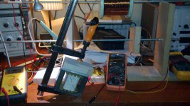
Also I meassured the idle current to be 150mA on the primary. Yikes! About 35 watts at idle and unloaded.
Anyway, everyone like pictures so here is one of the transformer while checking the inductance... And do not mind my very tidy workbench... It
it mostly clean..
trobbins: I tried with the clamp. It didn't do very much difference. Yes, you are correct about the welds was along the gap lite. Good info there! Great!
Tony: About more turns on the primary... You mean more turns to lower the flux? If I go for 1 T it will be 668 turns instead of 557. That is better? Yes I read somewhere that one should always optimize for 50-50 on available window.
DF96: As I do not want to weld it back together before knowing if it will work, I think I will do as you say and repack it. Inductance is very low, about 0.6H. Not very good? I meassured another transformer (a lot smaller though) and it was about 3 H.
Also I meassured the idle current to be 150mA on the primary. Yikes! About 35 watts at idle and unloaded.
Anyway, everyone like pictures so here is one of the transformer while checking the inductance... And do not mind my very tidy workbench... It
it mostly clean..
Last edited:
How many watts was the light bulb you used to make the test?
I think that is very important!
And acording to my calculations ,for a 15,5 cm core, and 230V /50Hz you should have 736 turns in the primary!
I divide 50 by the core size,and i get the turns per volt,and it always works ok!
Silvino
I think that is very important!
And acording to my calculations ,for a 15,5 cm core, and 230V /50Hz you should have 736 turns in the primary!
I divide 50 by the core size,and i get the turns per volt,and it always works ok!
Silvino
There is no 35W at idle - it's inductive (reactive) current. If you had a chance to see transformers based on C wound cores - you would non miss strainer bolts and tape around to push haves really hard together. I vould check is the E-I parts fit. You may assembled them not the way they were. It seems that the only solution would be to make such a band clamp.
BTW 150 mA at the size shown is not that bad. No point of reducing the flux unless you are stray field concerned guy. It may num as well - gluing the halves, impregnation of the winding will fix that, but not the idle current.
You may as well try to find fine iron powder in glue - for that patricular problem...
P.S. Turns calculations are correct, but you have to check fill factor of the core - its probably around 0.8
EDIT http://automationnotebook.com/2009-Issue-15/technology-brief-issue15-2009.html
Last edited:
As I have no clue what iron is in the core, I decided to try 1.2 Tesla in the
calculations. So permeability is unknown and estimated to handle the flux density.
Here is some data I used for the calculations:
Core size: 15.5cm2
Primary voltage: 230 VAC
Flux: 1.2 Tesla
Frequency: 50 Hz
Based on that, it looks like you'd require 619 turns on the primary for a flux density of 1.2Wb/M2. If you went with 1.0Wb/M2, then it would be 742 turns. You don't have enough primary turns there, so I'd expect saturation. I would especially expect it if the original xfmr was fried real good, as that could change the magnetic properties of the lams.
If you aren't getting any secondary voltage, then I'd look for a short circuit somewhere. That should not be happening.
Miles,
Apparently you use another formula to calculate the flux density.
It seems that Jörgen uses the same is I do, which is 45 x 230 / (15,5 x 668) for a flex density of 1T, where 668 is the number of primary turns.
That's why I asked him to measure once more the core dimensions, as the Afe in square cm's is not exactly the geometric size (there is loss).
Besides, the saturation treshold depends also on the quality of the iron.
It ranges from over 1,6T for a good quality 0,35mm lamination to 1,3T for a mediocre quality 0,5mm lamination.
So we have to know what size/quality the core is.
How many watts was the light bulb you used to make the test?
I think that is very important!
And acording to my calculations ,for a 15,5 cm core, and 230V /50Hz you should have 736 turns in the primary!
I divide 50 by the core size,and i get the turns per volt,and it always works ok!
Silvino
Hello Silvino,
I used a 60 W light bulb. That looks like one of them good and easy to remember formulas. Thanks!
There is no 35W at idle - it's inductive (reactive) current. If you had a chance to see transformers based on C wound cores - you would non miss strainer bolts and tape around to push haves really hard together. I vould check is the E-I parts fit. You may assembled them not the way they were. It seems that the only solution would be to make such a band clamp.
BTW 150 mA at the size shown is not that bad. No point of reducing the flux unless you are stray field concerned guy. It may num as well - gluing the halves, impregnation of the winding will fix that, but not the idle current.
You may as well try to find fine iron powder in glue - for that patricular problem...
P.S. Turns calculations are correct, but you have to check fill factor of the core - its probably around 0.8
EDIT Technology Brief - Issue 15, 2009, Transformers: Application, Construction and Efficiencies, Part One of a Two-Part series
Thanks for the info! Very interesting! Much appreciated!
Oopps! Something in my head popped up when I read your comment about there is no 35W at idle since the reactive load.
One thing to put on my "refresh memory"-list. Jörgen,
What are the exact dimensions of the core (is it EI120 or?) and what is the height of the stack.
What is the thickness of the laminates (0,35mm, 0,5mm or..)?
Hello Pieter,
The bobbin is a M 102b/54. It has space for a 34.6x54.0mm core.
Height is 61 mm (if you mean where winding is?)
I meassured the core and it's 34x53.5mm.
The thickness of the laminates is 0.5mm.
Thanks!
As I was at work then I first posted this question I made a misstake about the
core size. As I wrote to Pieter the bobbin is a M 102b/54.
The bobbin has room for a 34.6x54.0mm core and I meassured the
core to actually 34x53.5mm.
Some stacking factor (lets say 0.8) and the will be a effective core size of
14.552cm2. Correct?
And assuming this core (even after it's been abused and steel properties might have changed) can handle 1.2 T and using calculations from Coils and transformers gives about 658 turns, and since the "magnetic flux buildup average RMS"-stuff leaves me with 586 turns.
Correct?
Head hurts now!!!
Based on dimension and grade (0,5mm) my estimate is that the core can supply around 250 watts of secondary power.
Your assumption of max 1,2T is OK, but my advice is to calculate what the transformer must supply for your application, and use the winding space such that you stay well under 1T.
After all that will give you a better transformer in terms of temperature and stray fields.
The lower T will give less secondary voltage regulation but that is not that important.
- Status
- This old topic is closed. If you want to reopen this topic, contact a moderator using the "Report Post" button.
- Home
- Amplifiers
- Tubes / Valves
- Transformer winding - mysterious!