About more turns on the primary... You mean more turns to lower the flux? If I go for 1 T it will be 668 turns instead of 557. That is better? Yes I read somewhere that one should always optimize for 50-50 on available window.
yes, in my designs, i go for 0.9T to get lower magnetizing current, it looks to me that you have room for more primary turns...
I just inserted a paper thin gap into a microwave oven transformer, at 50vac on the primary it increased the magnetising current about 30%.
exciting the secondary of another at 140 vac, magnetising current went from 12 ma to 18 with one sheet of paper (2.5 mills) and from 12 to 23 ma with two sheets of paper (5 - 5.5 mills)
this implies the core is about equivalent to a 5 mill air gap, at ~.1T flux density. which is really bad, implying a permeability of only 400.
if your magnetising current copper loss is negligible like it should be, then watts lost at no load won't change significantly, even with a .002 inch air gap.
once the core is welded there is nothing to be gained from separating the laminations, the damage done to them during the separation will make it worse.
Miles,
Apparently you use another formula to calculate the flux density.
I use the standard xfmr formula:
Vn= 4fSB
Where:
Vn -- Volts per turns ratio
f -- frequency in Hz
S -- core X-sectional area in M2
B -- flux density in Wb/M2
I never saw that other formula before, and it looks to be some sort of rough approximation. I've used the above for xfmrs working at AC line frequencies to high frequency, high voltage xfmrs.
Based on dimension and grade (0,5mm) my estimate is that the core can supply around 250 watts of secondary power.
Your assumption of max 1,2T is OK, but my advice is to calculate what the transformer must supply for your application, and use the winding space such that you stay well under 1T.
After all that will give you a better transformer in terms of temperature and stray fields.
The lower T will give less secondary voltage regulation but that is not that important.
This is great information! Thanks!

I will crunch the numbers for 0.9T and add the extra turns to the primary,
then assemble the transformer (now alternating the Es and Is)
Will test this tonight and report back!
yes, in my designs, i go for 0.9T to get lower magnetizing current, it looks to me that you have room for more primary turns...
I will try a 0.9T. Yes, there is room I guess. Secondaries will be perhaps 250-0-250, 3.15-0-3.15, 2.5-0-2.5 and a 52 volt.
Thanks for the info!
Imho, unless you break up the E's and I's and refit as interleaved, or learn how to weld, or use a ferrofluid style glue, or mill the core mating areas to sufficient flatness, then your aim of efficiently reusing the core is somewhat thwarted.
Well, welding I do know.
I only have a MIG though.But I've already broken up the E's and I's so now I can stack them back together.
Thanks for info!
I just inserted a paper thin gap into a microwave oven transformer, at 50vac on the primary it increased the magnetising current about 30%.
exciting the secondary of another at 140 vac, magnetising current went from 12 ma to 18 with one sheet of paper (2.5 mills) and from 12 to 23 ma with two sheets of paper (5 - 5.5 mills)
this implies the core is about equivalent to a 5 mill air gap, at ~.1T flux density. which is really bad, implying a permeability of only 400.
if your magnetising current copper loss is negligible like it should be, then watts lost at no load won't change significantly, even with a .002 inch air gap.
once the core is welded there is nothing to be gained from separating the laminations, the damage done to them during the separation will make it worse.
Well, I now have taken the E's and I's apart so in that case I've already made it worse.

Anyway, I guess we will see what happens later tonight when I add more turns and put it together.
As I was at work then I first posted this question I made a misstake about the
core size. As I wrote to Pieter the bobbin is a M 102b/54.
The bobbin has room for a 34.6x54.0mm core and I meassured the
core to actually 34x53.5mm.
Some stacking factor (lets say 0.8) and the will be a effective core size of
14.552cm2. Correct?
And assuming this core (even after it's been abused and steel properties might have changed) can handle 1.2 T and using calculations from Coils and transformers gives about 658 turns, and since the "magnetic flux buildup average RMS"-stuff leaves me with 586 turns.
Correct?
Ok! for the core size of 14,5cm2 with a 10.000 Gauss iron (good quality)
you divide 45 by core size ,and you get 3,1 turns/volt ,than for 230V you will need 713 turns. For 9000 Gauss iron ,divide 50 by core size,and will need 3,4 turns/volt,therefore for 230V will need 782 turns! Easy and never fails.
Silvino
Head hurts now!!!
Not appropriate for audio indeed,but ok for a 50 Hz power transformer!GOOD cold drawn oriented steel flux density would be 12.500 -14.000 and saturation around 17.000. It's definetely not appropriate for audio, but still steel would not saturate with the # of turns used.
LATEST UPDATE!
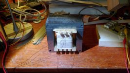
Well, after adding another 230 turns, now totally 792 turns and repacking the core alternating E's and I's as in a "normal" transformer...
Transformer is now very quiet (and just temporary held together), draws about 45 mA in idle and 20 turns on the secondary gives 5.9 volts.
So that gives about 3.39 turns/volt.
So I am very happy now! Now I have to take some notes and see what I've
learned this far.
I wonder what this all means regarding the core material I have.
Since it obviously did not work with the previous number of turns we can say that 1.2T did NOT work? And of course... Now the E's and I's are not welded so "no" air gap.
Will let it run for a while now and check temperatures.
To all who has written in this thread: MANY MANY THANKS!!!
Attachments
So that gives about 3.39 turns/volt.
sounds just about right for that size traffo....
LATEST UPDATE!
Well, after adding another 230 turns, now totally 792 turns and repacking the core alternating E's and I's as in a "normal" transformer...
Transformer is now very quiet (and just temporary held together), draws about 45 mA in idle and 20 turns on the secondary gives 5.9 volts.
So that gives about 3.39 turns/volt.
So I am very happy now! Now I have to take some notes and see what I've
learned this far.
I wonder what this all means regarding the core material I have.
Since it obviously did not work with the previous number of turns we can say that 1.2T did NOT work? And of course... Now the E's and I's are not welded so "no" air gap.
Will let it run for a while now and check temperatures.
To all who has written in this thread: MANY MANY THANKS!!!
So ,means that you have a 9000 Gauss iron ,and in post#29 ,my calculation
was 3,4 turns/volt wich makes for 230V total of 782 turns!
Further to alexburg's comment. You can use a variac (if you have one) or a Tx with 240/260 primary taps as autotransformer, or if you have a (say) 280V secondary from a valve amp. Knowing whether the mag current is pro-rata or starting to go up more rapidly is good info.
Don't forget to insulate the clamp bolts if you finally chassis mount the core horizontally.
Ciao, Tim
Don't forget to insulate the clamp bolts if you finally chassis mount the core horizontally.
Ciao, Tim
- Status
- This old topic is closed. If you want to reopen this topic, contact a moderator using the "Report Post" button.
- Home
- Amplifiers
- Tubes / Valves
- Transformer winding - mysterious!