I accdently posted in this in new members, I appologize.
Strange and unexplained event on a cathode resistor of 10 ohms, 1/2 watt, Xicon brand suddenly racing up to 250 to 350 ohms. They are supposed to be rated to 350V. This has happen three times now, different tubes, different sockets, different times. I caught the event twice after ruining one tube. The tubes are NOT shorting, the resistor is NOT popping. The tube which was damaged, now draws considerable more plate current than before, the other two are OK and still the same. Tubes tested on a restored and calibrated Triplett 3444.
The amp is a restored Sherwood 5500 II, hot-rodded with outstanding parts, except these Xicon resistors. Plate is 405, screen is 397, grid is pot adjustable to get 22ma across the 10 ohm resistor so the tubes run quite cool. The amp is never run more than 2/3 open driving 8 ohm speakers.
Everything checks out as OK circuit wise so I am stumped what is making these resistors fail unless it is simply the brand.
Any ideas????
Sounds odd. How did you measure those resistors?
Oh and I might just be my own dumb self here, but how does a cathode resistor that apparently rises in value kill a tube? 'Faulty' cathode-R resistance rises --> voltage drop over the resistor becomes larger --> grid becomes more negative compared to cathode --> tube squeezes and current drawn decreases --> voltage over cathode resistor drops --> situation stabilizes a round a different, lower idle current than before. A cathode resistor shorting certainly would be more worrying. Am I missing something?
Oh and I might just be my own dumb self here, but how does a cathode resistor that apparently rises in value kill a tube? 'Faulty' cathode-R resistance rises --> voltage drop over the resistor becomes larger --> grid becomes more negative compared to cathode --> tube squeezes and current drawn decreases --> voltage over cathode resistor drops --> situation stabilizes a round a different, lower idle current than before. A cathode resistor shorting certainly would be more worrying. Am I missing something?
Last edited:
fluke 87 III to measure everything.
I have no idea if the resistor "killed the tube" or not, but it did draw 2x current than before on the Triplett so it could not be matched up again.
But the question is...why would these resistors jump up in value like that. This also happen in a Fisher 500C which I did not mention in the first post.
Has this happened to anyone else or are they a bad Chinese batch of junk resistors.
I'm guessing the 7591s used are current production. Current production 7591s are intolerant of the liberties 1960s manufacturers sometimes took with the published grid to ground resistance value limit. The tubes may have run away and overheated the 10 Ω "idle" current set resistors. It doesn't take much to "cook" 1/2 W. rated parts.
What's the grid to ground resistance value Sherwood used? Please post a link to the schematic.
BTW, what is the material construction of the troublesome parts?
What's the grid to ground resistance value Sherwood used? Please post a link to the schematic.
BTW, what is the material construction of the troublesome parts?
G&L -- I'm guessing that since you said this amplifier has been hot rodded, there has been additional capacitance added to the power supply, and the screen grid take off point in particular. If this is the case, I am rather certain that this is the reason for your problems. You are describing the symptoms of screen instability to a "T", which can do light damage to cathode bias measuring resistors and tubes, making the resistors read way high and/or the tubes off spec on the one hand, or in the worst cases, cause an arc and take the resistor and tube out altogether. You say the tubes did not arc. But I bet more happened than you suspect.
If capacitance has been added to the screen grid circuit, it can cause screen instability in new production or NOS power tubes that are run in fixed bias at voltages that are near the max screen voltage rating, and also nearly equal to that of the plate voltage. It is particularly prone to happen in high value Gm tubes such as the 7591 under these conditions. The answer is to add screen stability resistors to each output tube, that will eliminate this kind of problem. 100 ohm 1/2 watt resistors of nearly any type construction will do. Add one at each tube between the screen terminal, and the source providing power for it.
If resistors such as these are not in place, it is likely that they will solve your problems.
Good luck!
Dave
350 Volt rating is total nonsense for a 10 ohm resistor. 2.24 Volts puts it at full power. What is the normal operating Voltage? Is it simply getting fried?
BTW resistor Voltage ratings are for resistors below the dissipation limits. For a 1/2 Watt resistor the 350 Volt limit starts at 245 K Ohms and up. IOW a MAX of 350 Volts OR 1/2 Watt.
G²
BTW resistor Voltage ratings are for resistors below the dissipation limits. For a 1/2 Watt resistor the 350 Volt limit starts at 245 K Ohms and up. IOW a MAX of 350 Volts OR 1/2 Watt.
G²
as to the grid circuit going open, I don't think so the diodes are Fairchild Stealth. From there on each channel has its own pot to set tube pairs ( the original was common to all 4).
The capicitors in the entire amp are new, Atom TVA, F&T for the power supply, United Chemicon and Nichicon Silk caps in bias.
As to dcgillespie's reply, the screen has a wire wound 480 ohm/5 watt feeding all 4 tube screens (this is stock), power taken from the plate, extra capacitance was added in the power supply from the F&T being 50uf instead of 40uf, but it is fed into a 33 ohm 10 watt resistor before distribution into the general circuits...I can't see that as the culpret. Since this has now happen 3 times, you may have a point add in a discrete resistor to each tube. As for the tubes, they are near new EH and test fine, with current draw within 1% each. The tubes did not arc because I watch and listen like a hawk, anything that changes(sound wise) has me on top of it asap. This last episode did have the tube giving a yellow ( I think) glow at the top, but I had the amp off in a heart beat so I didn't let the occurance go further, and the tube tests fine.
The BIG question is that this has also happen in a Fisher 500c that I restored for a friend last year.
I'm guessing the 7591s used are current production. Current production 7591s are intolerant of the liberties 1960s manufacturers sometimes took with the published grid to ground resistance value limit. The tubes may have run away and overheated the 10 Ω "idle" current set resistors. It doesn't take much to "cook" 1/2 W. rated parts.
What's the grid to ground resistance value Sherwood used? Please post a link to the schematic.
BTW, what is the material construction of the troublesome parts?
metal film resistors. Yes, I am conscience of the liberal grid resistors used by many at 300K. The Sherwood stock is 150K, and .068 coupling cap so the freq. pole for the tube doesn't seem out of line.
Strange and unexplained event on a cathode resistor of 10 ohms, 1/2 watt, Xicon brand suddenly racing up to 250 to 350 ohms.
"Xicon" sounds like metal film resistors. If the value is rising that high, then there has been partial poofage that has damaged the internal metal tracks.
The tubes did not arc because I watch and listen like a hawk, anything that changes(sound wise) has me on top of it asap. This last episode did have the tube giving a yellow ( I think) glow at the top, but I had the amp off in a heart beat so I didn't let the occurance go further, and the tube tests fine.
That yellow glow sounds suspiciously like glowing screen grids. From all indications, your finals are rolling over and dying on you. Don't necessarily believe everything a tube tester tells you. I've seen 6KD6s that tested out just swell on a tester, and yet arced when put into service as a colour TV HD final. They either may, or may not, work under less demanding service (i.e. RF finals) but there has still been some damage done internally, whether that's an intermittent short, or gas induced run away, or just plain lousy tubes.
Glowing screens means run-away for some reason, and that could damage cathode current sense resistors.
Thanks Miles...well you are the second to suggest the screen are the likely cause. I know that a tester even a great one can't reveal all at 250 for a plate and screen, and I have set that tube aside.
dcgillespie suggested individual resistors for the screens (stock is one 470ohm/5watt feeding all with a 25uf cap following the resistor before distribution to the screens.
I'd post a schematic, if someone can suggest how.
dcgillespie suggested individual resistors for the screens (stock is one 470ohm/5watt feeding all with a 25uf cap following the resistor before distribution to the screens.
I'd post a schematic, if someone can suggest how.
but only the cathode resistors in either amp? Do they have the same g1 biasing set-up?
Are the adjusting pots in parallel with a resistor or does all the bias run through the pot only?
Does the bias voltage come up before the B+ on start-up?
I know these all seem slightly condescending, but its the obvious we often miss...
10 ohms @ 20ma means only .004w disipation, so its hard to imagine that even a dud resistor is going to be working hard unless something upstream has turned to custard...
I'd post a schematic, if someone can suggest how.
You can upload graphics, using the "advanced" posting method. Look down the page to Additional Options. Just make sure you don't exceed the pixel limit. In the past, IrfanView proved useful for resizing graphics. I've had trouble of late (perhaps it's Windows-7). YMMV.
but only the cathode resistors in either amp? Do they have the same g1 biasing set-up?
Are the adjusting pots in parallel with a resistor or does all the bias run through the pot only?
Does the bias voltage come up before the B+ on start-up?
I know these all seem slightly condescending, but its the obvious we often miss...
10 ohms @ 20ma means only .004w disipation, so its hard to imagine that even a dud resistor is going to be working hard unless something upstream has turned to custard...
After the stealth diodes is the primary smoothing cap, then each pair has its own ground/voltage divider resistor and bias pot trimmerwith a smaller smoothing cap. The trim is miniman the voltage is only -25 to begin with and I have it set at a cool 20ish. I thought about slow start up but am not there yet, the basic circuit is stock 1962. I just rebuilt with high end parts including teflon caps and occ wire, quazi-star ground, Cree and Fairchild diodes...that sort of thing. Sounds daziling.
I do suspect that it may involve the screens somehow, unless the resistors are just a bad bunch.
I see about posting the schematic today (thanks Eli for that tip).
Thanks for providing the schematic. It surely makes it easier to understand the circuit you are dealing with.
While I understand that your modifications to the original design have been minimal, this is still a design that is inherently at risk for screen grid instability. You may have in fact had a bad run of tubes or resistors, but I have serious doubt that this is actually your problem. The low impedance SS voltage doubler PS and the conditions the output tubes operate under all strongly favor the problems you are having. The installation of separate screen stability resistors hurts nothing, and eliminates that issue as a possible cause. However, once a tube has had any kind of (near) arc event, it is my experience that at the very least, the tube will still be prone to instability going forward.
There were a number of designs that had this issue from the start, that the manufacturer never could resolve. The Eico HF-89 is a classic example that would arc even the best output tubes back in the day. The installation of screen stability resistors solves the issue completely.
Dave
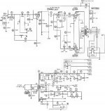
here is the power output section of the schematic, nothing unusual by design just a Williamson common consumer amp. The file is a JPEG and not to easy to fit into 198K to up load, if it is blured, I'll try something else:
This isn't a Williamson inspired topology which may be recognized by the use of a split load inverter (aka cathodyne) driving a differential stage. This one is just a voltage amplifier stage AC coupled to a split load inverter. It does however share the Achilles heal of the Williamson in that it has two LF poles inside of the feedback loop..
Last edited:
- Status
- This old topic is closed. If you want to reopen this topic, contact a moderator using the "Report Post" button.
- Home
- Amplifiers
- Tubes / Valves
- cathode resistor sudden rising value on 7591