Originally, the SC-22 preamp uses a BC114 as input transistor in the RIAA stage. I have restored my preamp according to a modified circuit shown below with a BC109 as input transistor. However, I used a BC550 as a modern low-noise substitute, keeping the same biasing (resistor) scheme. The problem is that there is no output at all from the disk stage.
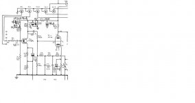
As I have practically no knowledge of solid state electronics I would like to ask whether the new transistor is properly biased. As can be seen from the attachment, there is a 15V zener-regulated supply with 680K-82K base bias and 68K at the collector and emitter resistor 15K and 1.5K to ground.
I tried the internet for biasing texts and calculators but there are so many variables that I got lost. Maybe some of you can help me establish whether the BC550 is properly biased. I know my problem could be caused by something else but this being my only deviation from the circuit I think it's best to clear it first.
Sorry for posting what may be a trivial/newbie question, and I thank you for your help.
Joe A
Attachments
Difficult to answer this before you give some dc-voltage readings.I would like to ask whether the new transistor is properly biased.
So what is the dc-voltage at C, B and E ?
If there is no output from the amplifier, this hardly is due to wrong bias.
Difficult to answer this before you give some dc-voltage readings.
So what is the dc-voltage at C, B and E ?
If there is no output from the amplifier, this hardly is due to wrong bias.
Thanks artosalo for your reply. I took voltage readings on all the anodes and they are 10 to 15% less than specified. Voltages at C, B and E are all zero. The voltage at the top of R9 (220K) is almost 260V-dc (should be 300V). But after R44 (150K) reading is 0.
This leads me to conclude there is no voltage at the transistor collector. I will change to a larger HT transformer to bring the supply voltage to the unit up to the specified 350V. Immediately after the PS there is a 6.8K resistor directly feeding the CF stage. Here, instead of the 305V specified I'm getting 290V. Further along the various stages the voltage difference continues to increase with the largest difference on the disk input stage as stated above.
So I'll modify the power supply and see whether that solves the problem. Meanwhile, any comments, advice would be welcome.
Regards,
Joe A
PS. Zen Mod, I find it strange that you suggest a PNP where an NPN transistor is called for. Maybe you said it with tongue in cheek. Or else I'm missing something. Thanks anyway for setting me thinking...
....
PS. Zen Mod, I find it strange that you suggest a PNP where an NPN transistor is called for. Maybe you said it with tongue in cheek. Or else I'm missing something. Thanks anyway for setting me thinking...
sorry - my mistake
I looked at schematic , without reading "BC109" and somehow saw emiter arrow pointing in .....
Yes, I measured a short circuit between the zener and large capacitor which are on a separate board. With this board disconnected there was no short between R45 - C33. I then reversed the orientation of the zener (with its black band facing the large capacitor -ve. Previously the zener band was facing +ve which i believe is the correct way).
That way (with zener band facing -ve) I didn't measure a short but when I plugged in the unit to the power supply I couldn't get any voltage at C, B, or E. When I checked again there was shortcircuit between R45-C33 and the board with the zener and large electrol. cap.
As it is late here, I left it at that to see what you have to say. At least now I think I have localised the problem, thanks to your help.
Regards.
Hello friends, this is really frustrating. I unsoldered and checked R44, R45, the smoothing capacitor (99uF), C33 (cct in post #1) and they're all OK. Also changed the 10,000uF to a smaller 47K. I removed the hand-written circuit and took new readings without it. The full HT (275V) is being developed across R44. I immediately shut off to avoid causing more harm (although this might have happened already!) to seek your help. Any ideas and/or suggestions, please.
Thanks.
Thanks.
Not sure why you have a 10000uF cap in there, the time constant for that to charge would be very long. Large electrolytics also have significant leakage currents - in this case possibly an appreciable % of the overall current available in the circuit.
I'd put the design back to stock. Sure the original transistor was not germanium? If that is the case (and I haven't checked) the bias network will need to be modified.
Clearly there is a short somewhere. I'd remove all mods and figure out what is going on. Biggest harm here is a popped transistor, no big deal IMHO.
Problem Solved - TNX
It wasn't a shorted component after all. A very small stray strand from the -ve side of the input screened cable must have been touching the pc track carrying R44 and surrounding circuitry to the input transistor. That's the beauty of p-2-p construction in DIY projects (despite the convenience, aesthetics and compactness of pcb-based units)!!
I wish to thank all posters who provided me with the necessary moral and technical support to successfully complete the restoration of my Radford SC-22 which I must say is a very good preamp, despite its being a more than 50-year-old design!
Best regards,
Joe A
- Status
- This old topic is closed. If you want to reopen this topic, contact a moderator using the "Report Post" button.
- Home
- Amplifiers
- Tubes / Valves
- Radford SC-22 Restoration - Input Transistor Biasing Question