ok, lets see, back to back transformers for an HT feed. Back to back in parallel or in series? Parallel could introduce inrush issues to the rectifier stage. Series could cuts your secondary winding current ability since the voltage on the primary probally won't be double of what a single tranny would see, unless you use 220 on the primaries.
good point is that in series, at idle, less idle current being drawn as a result of twice the impedance and inductance while maintaining 120 volts.
good point is that in series, at idle, less idle current being drawn as a result of twice the impedance and inductance while maintaining 120 volts.
We have the luxuary of "220" volt mains here , so a 220v primary as the primary.. like this..
220VAC > 12VAC > 12VAC >220 VAC
Done it with conventional E-I transformers a million times to great effect (you can even scavenge the heaters off the "inbetween" stage)
Transformers will be identical.
220VAC > 12VAC > 12VAC >220 VAC
Done it with conventional E-I transformers a million times to great effect (you can even scavenge the heaters off the "inbetween" stage)
Transformers will be identical.
You may have a bit more inrush current, easily taken care of with a inrush surge suppressor (varistor) or an appropriately rated delay blow fuse. Efficiency should be a bit better than with the typical EI transformers.
Should conducted EMI be a concern a common mode choke on the primary of the first transformer in the chain should take care of most of it. (Coiltronics and Coilcraft here in the US make suitable chokes, not sure who in the UK does.)
Should conducted EMI be a concern a common mode choke on the primary of the first transformer in the chain should take care of most of it. (Coiltronics and Coilcraft here in the US make suitable chokes, not sure who in the UK does.)
Thanks kevinkr and speakerfritz.
If you ground the "centre tap" of the "inbetween" stage, it makes a common mode choke anyway ... love something for nothing")
I'd have to think about that, but I don't think that is correct because the secondary windings share the same core with the primary windings and the coupling mechanism for common mode HF noise is largely electro-static in transformers so the signal will still appear as common mode and since it is capacitively coupled it will not be rejected in the receiving transformer either.
Were the above center tap comment really true you could technically make this argument with all center tapped full wave rectifier circuits from an HF EMI standpoint and from experience that is absolutely not the case.
Power toroids typically have pretty high interwinding capacitance and rather low leakage inductance which is not ideal from the standpoint of rejecting conducted EMI on the power lines.
EI transformers are somewhat effective at rejecting common mode HF EMI by virtue of their significant leakage inductance.
Obviously common mode LF is pretty effectively rejected in any transformer coupled application.
Grounding center taps in audio (not power) transformers usually results in degraded CMRR because the windings are usually not perfectly symmetrical and small differences in capacitances, dcr and electrical length all conspire to degrade balance. They are usually floating for this reason.
Last edited:
Kevin:
Is it not true that in a traditional xfmr with electrostatic shield, that there is likely high capacitance between primary-shield and secondary-shield? Since the shield is grounded, tho, the shield acts as a guard and effectively eliminates capacitance between primary and secondary. RF or noise, once shunted to ground, becomes benign.
In the same regard, the shared #1 secondary and #2 primary take the place of the shield. Yes, there is high capacitance to #1 primary and #2 secondary, but since the middle portion is grounded, it behaves exactly like the e-shield.
At least that's the way I always figured it. IMO, best to go with a single shielded xfmr anyway.
Kevin:
Is it not true that in a traditional xfmr with electrostatic shield, that there is likely high capacitance between primary-shield and secondary-shield? Since the shield is grounded, tho, the shield acts as a guard and effectively eliminates capacitance between primary and secondary. RF or noise, once shunted to ground, becomes benign.
In the same regard, the shared #1 secondary and #2 primary take the place of the shield. Yes, there is high capacitance to #1 primary and #2 secondary, but since the middle portion is grounded, it behaves exactly like the e-shield.
At least that's the way I always figured it. IMO, best to go with a single shielded xfmr anyway.
Yes, what you say is true about the electro-static shield which is why I have generally preferred transformers with them. Antek is now offering them as an option but currently don't have stock - I think this will go a long way towards answering the conducted emi issues in toroids assuming of course that the inductance in the shield and ground wire is low..
WRT to the center-tap, your comment would be most true at the low end of the EMI spectrum, the winding inductance would prevent the HF/VHF conducted EMI from actually seeing that grounded center tap. I've certainly seen plenty of conducted emi on the outer legs of center-taped secondaries. (A few uH of winding inductance for example is enough for distant lightening strike generated transients to blast right through..)
For the same reason I haven't found the back to back transformer approach to offer the kind of isolation I would like to see theoretically speaking.
When I was still in business a local transformer house built all of my power transformers to my specifications which included an electro-static shield between the primary and secondary. Sadly they sold the business and I can no longer get good transformers built locally. Some boutique vendors cannot be persuaded to place and electro-static shield between primary and secondary.
In truth I think a common filter ahead of the transformer solves most of these issues, but of course there are the endless arguments about the effect they have on the sound.. A popular tweak in many cases is to remove the filter, and in some cases I suspect the lower current rated devices have appreciable dcr which in some circumstances might be audible I suppose. I've never reliably been able to detect a difference, but have been able to convince myself on the spot that I did..
After experiencing problems with RF in my first few tries with DIY tube gear, I will only use shielded transformers from now on (IT and OPT excepted, of course).
For a good source, I think you may have recommended ElectraPrint to me a few years back; I have been very happy with the results, albeit the pricing is high. You also have to be specific about how you want the transformer to operate (loaded or unloaded voltages, etc). But in the end you get a great product.
As much as I like Lundahl's products, I have not had the best results with their power transformer. Let in a lot of noise (I have an AC drive running my well pump, and it puts out a ton of HF hash). I don't believe you can get shields with their C core products.
In applications of my Filament Regulator kits, I find that an isolating transformer can be very effective where there's a lot of mains noise.
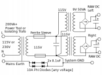
The first transformer has its chassis connected to mains Earth. The secondary windings are connected to system GND (B-Return), which is only returned to safety Earth through 10A diodes - these give quite good EMI isolation for common-mode noise. !! Caution - Only use this diode connexion if you are SURE you know what you are doing!!
Also, be sure to use some Ferrite sleeves or toroids on the secondary wiring to absorb the really high frequency noise. Wind 3 or more turns through a toroid. Choose a grade of ferrite designed for EMC purposes - the 'inductor' grades are not so lossy.
I should clarify that with filament heating (I normally use AC) the use of split bobbin transformers does a fine job blocking RF transmission. Not sure if anyone has had the opposite experience, but by the numbers pri-sec stray capacitance is fairly low.
Cores should always be grounded-- power, IT, OPT, input, whatever. Have measured surprising performance boost when grounding cores versus floating, but not w.r.t. RF. Phase balance and frequency response improves.
Cores should always be grounded-- power, IT, OPT, input, whatever. Have measured surprising performance boost when grounding cores versus floating, but not w.r.t. RF. Phase balance and frequency response improves.
I should clarify that with filament heating (I normally use AC) the use of split bobbin transformers does a fine job blocking RF transmission. Not sure if anyone has had the opposite experience, but by the numbers pri-sec stray capacitance is fairly low.
Cores should always be grounded-- power, IT, OPT, input, whatever. Have measured surprising performance boost when grounding cores versus floating, but not w.r.t. RF. Phase balance and frequency response improves.
I have a number of split bobbin types and they are excellent from an EMI perspective as you say, mine unfortunately made so much noise that after 4 yrs of use I retired them, and yes I replaced them with quiet-as-a-ghost toroids.
I try to ground transformer cores when they are accessible for grounding, if for no other reason than safety. I think it is a good idea for the reasons you state as well. (Have seen this effect with some UTC line to plate, and line to line transformers)
Rod's recommendation above with the isolation transformer is an excellent one.
Could be better to use toroids back to back since they normally have substantially lower windingresistance.
Using standard iron normally rises the inner resistance extremely.
Example: Using two 230 to 24V transformers, back to back, with 130ohm and 10ohm winding-resistance respectivly results in a output Z of over 2kohm. If using a 230:230V with 130ohm, 130ohm results in 260ohm.
Using standard iron normally rises the inner resistance extremely.
Example: Using two 230 to 24V transformers, back to back, with 130ohm and 10ohm winding-resistance respectivly results in a output Z of over 2kohm. If using a 230:230V with 130ohm, 130ohm results in 260ohm.
- Status
- This old topic is closed. If you want to reopen this topic, contact a moderator using the "Report Post" button.
- Home
- Amplifiers
- Tubes / Valves
- Back to back toroids