Hello All
I would like to create this subject to get some help from your side during my first tube amplifier building.
I hope more experience ppl will prevent me from my mistakes in advance. I will ask also for some trick and tips.
I infected tubes few months ago. I built my first tube machinery – preamp.
Bufor lampowy 2 x ECC82 + magiczne oczko by JAP
When I finished above project I got huge necessity to create something with real tube sound. Of course I started to look around how to build tube amplifier. After loooong reading of hundreds of websites I decided to build SE amplifier without NFB based on EL34. I started to collect tubes… and suddenly something inside told me… you need more power! I decided to build this: http://www.jogis-roehrenbude.de/Leserbriefe/Roessler-Amp/Schaltung-ES.gif from website Gegentakt-Verstärker in AB-Betrieb für EL34 / 6L6GC
Power supply has stabilization on each voltage http://www.jogis-roehrenbude.de/Leserbriefe/Roessler-Amp/Schaltung-NT-Neu.gif
Started from the beginning.
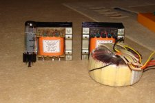
I bought matched pair of EL34 made by Electro Harmonix (plan to build just SE but witch matched ELs). Then I found very good transformer producer. You can see my transformers: freq range 7Hz – 180kHz, 18 sections, 4 and 8 Ohms output. Weight together with power supply transformer: 10,5 kg.
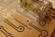
Next step was to create PCBs. To be honest I always used marker to create PCBs… but this time I said – it must be close to the perfect. I used thermo transfer method. First 3 PCBs I had to scrap. But after some experiments with printers and papers finally I get really nice PCBs. Now I know, I will use just this method for the future.
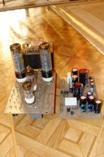
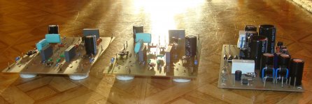
Another step was to collecting rest of the parts (some new, some recycling). Most expensive ones were transformers, but high voltage capacitors and tubes were not so cheap also. After soldering electronic parts with PCBs it’s look like on the pics.
Yesterday I just fix everything on the wood and it’s waiting for the weekend for wiring and first tests.
In the meantime I would like to ask you about few things:
b) Use the same stabilization like for EL34 but with 280V Zener diodes.
Thanks in advance for the feedback
Jap
I would like to create this subject to get some help from your side during my first tube amplifier building.
I hope more experience ppl will prevent me from my mistakes in advance. I will ask also for some trick and tips.
I infected tubes few months ago. I built my first tube machinery – preamp.
Bufor lampowy 2 x ECC82 + magiczne oczko by JAP
When I finished above project I got huge necessity to create something with real tube sound. Of course I started to look around how to build tube amplifier. After loooong reading of hundreds of websites I decided to build SE amplifier without NFB based on EL34. I started to collect tubes… and suddenly something inside told me… you need more power! I decided to build this: http://www.jogis-roehrenbude.de/Leserbriefe/Roessler-Amp/Schaltung-ES.gif from website Gegentakt-Verstärker in AB-Betrieb für EL34 / 6L6GC
Power supply has stabilization on each voltage http://www.jogis-roehrenbude.de/Leserbriefe/Roessler-Amp/Schaltung-NT-Neu.gif
Started from the beginning.
I bought matched pair of EL34 made by Electro Harmonix (plan to build just SE but witch matched ELs). Then I found very good transformer producer. You can see my transformers: freq range 7Hz – 180kHz, 18 sections, 4 and 8 Ohms output. Weight together with power supply transformer: 10,5 kg.
Next step was to create PCBs. To be honest I always used marker to create PCBs… but this time I said – it must be close to the perfect. I used thermo transfer method. First 3 PCBs I had to scrap. But after some experiments with printers and papers finally I get really nice PCBs. Now I know, I will use just this method for the future.
Another step was to collecting rest of the parts (some new, some recycling). Most expensive ones were transformers, but high voltage capacitors and tubes were not so cheap also. After soldering electronic parts with PCBs it’s look like on the pics.
Yesterday I just fix everything on the wood and it’s waiting for the weekend for wiring and first tests.
In the meantime I would like to ask you about few things:
- Please compare preamplifier section of this diagram (C1 R1) http://www.jogis-roehrenbude.de/Leserbriefe/Roessler-Amp/Schaltung-ES.gif and this one (R1, C1, R31) http://www.jogis-roehrenbude.de/Leserbriefe/Roessler-Amp/PPP-Schaltung.gif . What is the benefit coming from 2nd diagram (more modern) vs. 1st one? Preamplifier layout on my PCB is designed like on 2nd diagram.
- Currently I don’t have HV stabilisator VB408. But I have 2 ideas
b) Use the same stabilization like for EL34 but with 280V Zener diodes.
- We can find cascade of Zener’s diodes on the power supply http://www.jogis-roehrenbude.de/Leserbriefe/Roessler-Amp/Schaltung-NT-Neu.gif . I found diodes for total 420V. Capacitor is connected parallel to it. I found just 400V one (5%less than required). What do you think – will it survive or I will get nice BUM?

Thanks in advance for the feedback
Jap
Attachments
- Please compare preamplifier section of this diagram (C1 R1) http://www.jogis-roehrenbude.de/Leserbriefe/Roessler-Amp/Schaltung-ES.gif and this one (R1, C1, R31) http://www.jogis-roehrenbude.de/Leserbriefe/Roessler-Amp/PPP-Schaltung.gif . What is the benefit coming from 2nd diagram (more modern) vs. 1st one? Preamplifier layout on my PCB is designed like on 2nd diagram.
I don't quite understand how the first one is biased, so I'll leave that to the more experienced folks here. Seems like it's missing a cathode resistor for the top triode. I'm curious as to what is going on there, so I can't say why one would be better than the other. The only thing I can say, is that the second circuit (the one you are using) is a standard cascode amplifier with fixed bias. It should work fine.
Currently I don’t have HV stabilisator VB408. But I have 2 ideas
a) use just 3 – 4,7kOhms resistor instead of VB408 (like on the Jolida project - http://www.drtube.com/schematics/jolida/sj-502a.gif). I’ve used ECC83 and Russian 6N6P instead ECC99.
b) Use the same stabilization like for EL34 but with 280V Zener diodes.
The cascode amplifier for the input stage has virtually no PSRR, so it needs a clean supply. A resistor to drop the voltage might be good enough with sufficient filtering. You might want to split it and make a couple of RC sections. Your idea of using the same type of voltage regulator as is used for B+ is fine in principle. But you will be drawing much less current, so it may not regulate as well. Maybe some more experienced designers will comment.
I'd question the substitution of ECC83 for the ECC99. It has much higher gain and much lower gm. If you want the higher gain, fine. But you will get higher distortion unless you change the plate and cathode resistor values.
- We can find cascade of Zener’s diodes on the power supply http://www.jogis-roehrenbude.de/Leserbriefe/Roessler-Amp/Schaltung-NT-Neu.gif . I found diodes for total 420V. Capacitor is connected parallel to it. I found just 400V one (5%less than required). What do you think – will it survive or I will get nice BUM?
The three diodes in series will split up the heat dissipation between them. If you use a single diode, it will dissipate all the heat. If its dissipation rating is high enough it will work. You can increase the value of the series resistor to reduce the current through the diode. It's possible that a higher value resistor could reduce the performance of your regulator slightly. But I don't think it would have a significant effect.
Sheldon- We can find cascade of Zener’s diodes on the power supply http://www.jogis-roehrenbude.de/Leserbriefe/Roessler-Amp/Schaltung-NT-Neu.gif . I found diodes for total 420V. Capacitor is connected parallel to it. I found just 400V one (5%less than required). What do you think – will it survive or I will get nice BUM?
Last edited:
Actually, I wasn't completely accurate about the substitution of AX7 for ECC99. The gain would be similar - but a lot of other important parameters change. The input sensitivity is much different. The cathode resistor and feedback resistors would have to change. The plate resistor should be higher (and the compensation adjusted). In short, you can't simple switch. You'd need some redesign.
Sheldon
Sheldon
Hi
Regarding ECC83...sorry it was typing mistake. I will use ECC82 like it is on the diagram. The only one difference will be 6N6P instead of ECC99 (originally 12BH7 - like on the diagram from the 50's). I get information that this Russian 6N6P is really good tube. I bought NOS for incredible low price – 1,6€ / pc! ECC99 made by EH is 15€/pc. For sure it’s not a problem to pay more for better tubes but first I have to hear how this amplifier work (if it will work). Then it will be easier to invest more
Regarding next point - I'm worry about capacitor. It's 400V, and I will have 420V on it. I think it should survive. What do you think?
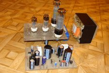
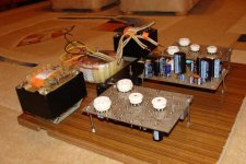
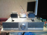
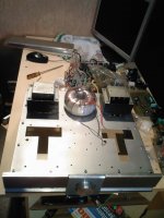
Latest prototype status (to kick off, to add some gadgets, to test it):
Regarding ECC83...sorry it was typing mistake. I will use ECC82 like it is on the diagram. The only one difference will be 6N6P instead of ECC99 (originally 12BH7 - like on the diagram from the 50's). I get information that this Russian 6N6P is really good tube. I bought NOS for incredible low price – 1,6€ / pc! ECC99 made by EH is 15€/pc. For sure it’s not a problem to pay more for better tubes but first I have to hear how this amplifier work (if it will work). Then it will be easier to invest more
Regarding next point - I'm worry about capacitor. It's 400V, and I will have 420V on it. I think it should survive. What do you think?
Latest prototype status (to kick off, to add some gadgets, to test it):
Attachments
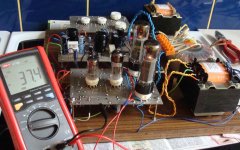
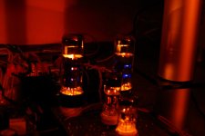
It kicks off today morning!
Just 1 channel, I need to wire 2nd one. I’ve used additionally stabilizer based on IRF820 + Zener’s diodes instead of both VB408. It is working perfect and cost is 8% of 2pc of VB408.
I have one question. I have pair of Electro Harmonics EL34’s. Can I buy another pair for 2nd channel or I have to buy 4 the same EL’s? Man who wired for me transformers said that I should buy 4 pcs of RFT or TESLA EL34. But the cost of these NOS tubes is quite big – especially the same 4pcs.
Crazy idea: what do you think to put NFB potentiometer on the user interface panel? I observed that it’s possible to change totally amplifier by NFB adjusting or switch it off.
Attachments
It started 2 days ago! Amazing sound. So crystal! I’m not and audiophile who are listening everything without tone adjustment – I like hi and low frequency a lot. But this amp sounds amazing without tone control! Most of CD’s I have don’t needed tone adjustment, but for some of them I need. It’s also possible to adjust sound by NFB – so I will put it on the user interface.
Could you counsel me some good, checked diagram for tone control (2 or 3 points) for tube amp?
Could you counsel me some good, checked diagram for tone control (2 or 3 points) for tube amp?
Project has not die
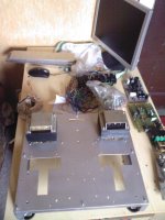
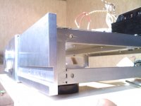
I had summer / ottom breake so no big progress was present. At today stage I have inner cage (main structure), outer alu plates (10mm) but it must be polished and painted. Also main plate is ready. I will fix all box parts to this cage. I hope to finish this amp to the spring 2012. I've just add few pics. What do you think?
I had summer / ottom breake
so no big progress was present. At today stage I have inner cage (main structure), outer alu plates (10mm) but it must be polished and painted. Also main plate is ready. I will fix all box parts to this cage. I hope to finish this amp to the spring 2012. I've just add few pics. What do you think?Attachments
- Status
- This old topic is closed. If you want to reopen this topic, contact a moderator using the "Report Post" button.
- Home
- Amplifiers
- Tubes / Valves
- Grommes 260A DIY report, questions, suggestions