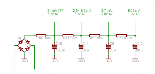
Schematic of PSU in question is attached below. Current draw per tap is indicated, as are measured AC ripples. Mains frequency is 50 Hz, I've measured the bridge diodes and they appear to be fine.
Do these AC ripple values make sense to you ? They seem to be awfully steep, considering the capacitances involved, it is almost as if some capacitors were duds
The problem I'm facing is hum which is apparently picked up in the input stage, guitar cable and so on. I cannot resort to GNFB just yet because I don't know what kind of insertion loss to expect from tone controls so I'm running things open-loop right now.
Attachments
Arnulf,
Normally the hum will reduce when the guitar is plugged in due to the low DC resistance of the guitar pick up. It is not uncommon for PSU caps to go dry or blow out in guitar amps.
Is it DIY built or what make is it.
Sometimes the reverb will become disconnected and this will cause pick up.
The other common fault is a bias problem or Leakey coupling cap.
What is each tap connected to?
Regards
M. Gregg
Last edited:
Arnulf, Can I suggest you short the grid input of the first stage to 0V (to eliminate anything before hand from influence) and check hum. Then obtain a known good electrolytic of suitable voltage and capacitance ratings (eg. 100uF), and solder directly across first filter cap (with correct polarity and safety concerns), and recheck hum and measured AC voltage levels. I presume your meter is rated for measuring ACV only with high DCV.
Ciao, Tim
Ciao, Tim
M Gregg: guitar is plugged in all the while. I wouldn't dare test the Oscillatingmachine without it
Zibi: yes, forming a LP filter with the following capacitor, and (in a way) "emulating" the "sag" of a vacuum rectifier. At least that was the plan ...
trobbins: amplifier topology is as follows: two cascaded common cathode stages, followed by a floating paraphase (= common cathode stage + inverting stage with full feedback), driving a PP pair of output pentodes. Volume potentiometer is inserted between 2nd common catode stage and the input of the phase inverter (= its common cathode stage).
With volume potentiometer turned all the way down there is esentially no hum at the speaker (whatever is left is merely a result of output tube disparity and isn't obtrusive).
With grid of 2nd common cathode stage (this is second stage after the input) shorted there is no hum at the output. Rotating the volume potentiometer will alter the speaker noise somewhat (it will be at its worst at some 50% of log pot's scale), but it doesn't sound like hum, more like some sort of oscillation. I can live with this, until I find out what *this* is and squash it. It's annoying but only if you hold your ear directly to the speaker so it doesn't bother me.
With grid of 1st common cathode stage (this is the input of the amplifier !) shorted any changing of the setting of the volume pot will change the level of hum as well, indicating that hum is coming from the 1st stage, or, in worst case, from second stage itself (potentiometer represents AC load for second stage). This is understandable, afterall the calculated gain of first stage is ~20, of second stage is ~20, of phase inverter (its common cathode stage) is ~40 and the gain of the output stage is just short of canceling out OPT transformation ratio (some 15-20x versus 25x).
The very first capacitor down the PSU chain is a known good one (pretty much, there's no certain thing in life than one's demise ). The rest are of unknown origin, it's reasonable to assume they are ~10 years old and of dubious quality.
Now what I'd like to know is whether the specified AC noise figures, measured at each lowpass R-C intersection, make any sense to you guys. If this first capacitor (a known good one) tames the ripple down to under 10 volts AC (= less than 5% of rectification ripple, DC ends up at 210-220V at its positive terminal), shouldn't all the follow-up capacitors reduce the ripple far more ? The ripple should have been negligible by the third capacitor, let alone fourth, which caters to both 1st and 2nd stage, yet I'm seeing almost 2V at the top side of 1st and 2nd stage anode resistors
Zibi: yes, forming a LP filter with the following capacitor, and (in a way) "emulating" the "sag" of a vacuum rectifier. At least that was the plan ...
trobbins: amplifier topology is as follows: two cascaded common cathode stages, followed by a floating paraphase (= common cathode stage + inverting stage with full feedback), driving a PP pair of output pentodes. Volume potentiometer is inserted between 2nd common catode stage and the input of the phase inverter (= its common cathode stage).
With volume potentiometer turned all the way down there is esentially no hum at the speaker (whatever is left is merely a result of output tube disparity and isn't obtrusive).
With grid of 2nd common cathode stage (this is second stage after the input) shorted there is no hum at the output. Rotating the volume potentiometer will alter the speaker noise somewhat (it will be at its worst at some 50% of log pot's scale), but it doesn't sound like hum, more like some sort of oscillation. I can live with this, until I find out what *this* is and squash it. It's annoying but only if you hold your ear directly to the speaker so it doesn't bother me.
With grid of 1st common cathode stage (this is the input of the amplifier !) shorted any changing of the setting of the volume pot will change the level of hum as well, indicating that hum is coming from the 1st stage, or, in worst case, from second stage itself (potentiometer represents AC load for second stage). This is understandable, afterall the calculated gain of first stage is ~20, of second stage is ~20, of phase inverter (its common cathode stage) is ~40 and the gain of the output stage is just short of canceling out OPT transformation ratio (some 15-20x versus 25x).
The very first capacitor down the PSU chain is a known good one (pretty much, there's no certain thing in life than one's demise
). The rest are of unknown origin, it's reasonable to assume they are ~10 years old and of dubious quality.Now what I'd like to know is whether the specified AC noise figures, measured at each lowpass R-C intersection, make any sense to you guys. If this first capacitor (a known good one) tames the ripple down to under 10 volts AC (= less than 5% of rectification ripple, DC ends up at 210-220V at its positive terminal), shouldn't all the follow-up capacitors reduce the ripple far more ? The ripple should have been negligible by the third capacitor, let alone fourth, which caters to both 1st and 2nd stage, yet I'm seeing almost 2V at the top side of 1st and 2nd stage anode resistors
Last edited:
It sounds like your ACV meter is not reading correctly. As you summise, the ACV should be down in the mV level with that amount of RC filtering - possibly the first capacitor may be in the V range.
Given your hum interrogation, I'd suggest looking at the heater supply you are using for the first 2 input stages. Do you have a humdinger pot? Are you using DC elevated AC heaters, or are you using a DC heater supply?
Ciao, Tim
Given your hum interrogation, I'd suggest looking at the heater supply you are using for the first 2 input stages. Do you have a humdinger pot? Are you using DC elevated AC heaters, or are you using a DC heater supply?
Ciao, Tim
All heaters are AC. Output tubes have one side of their heaters referenced to the ground (this has reduced noise considerably). Referencing them to 90V didn't make any difference versus connection to the ground. Input tube (dual triode, encompassing both 1st and 2nd stage) has its heater floating, referencing it to any potential (GND or 90V) didn't make any difference.
I did try DC supply for the first two stages ("wall wart" with DC output + 1000 uF) but it didn't make any audible difference whatsoever.
I don't have any other reliable high voltage capacitors handy, I'll have to buy some and replace existing ones to make sure filtering is allright. I can't think of any other reason for the ungodly large AC swings at the indicated points apart from meter possibly being defective, as you pointed out. Stores should be open, I'm not sure whether I'm going to make it to one today though.
It sounds like you didn't use a humdinger pot, but just connected one side of the heater to ground, or a DC voltage. I suggest it is well worthwhile trying a 100 ohm pot across the heater supply, and taking the wiper to ground, or more preferably to a well filtered +V DC (> about 10V, and < 100V). There is usually a sweet spot on the wiper setting where hum is nulled, and it is typically a lower level of residual hum than just grounding a heater end or mid-point, or using a fixed humdinger resistor.
The ripple you have does not look correct it should be based on the load "current drawn", to have "loaded the capacitor" to give values as high as you show! You say the cap is good something is not right.
What is the volt drop across the 100 Ohm ? The reason I ask is becase if one of the capacitors down the line is going short it will increase the volt drop. Our old friend >>>(Kirchhoffs current Law).
---------
Does it have a spring delay line unit "reverb"
If it does check the connections.
Regards
M. Gregg
Last edited:
"I've measured the bridge diodes and they appear to be fine."
I have found a weak diode to be one of the most common causes of hum. Do you measure the diodes out of circut (cut one end, measure, resolder). Did you use a diode tester, or an ohm meter ? If you have any unusally hot resistors, I would double check the diodes.
good luck.
I have found a weak diode to be one of the most common causes of hum. Do you measure the diodes out of circut (cut one end, measure, resolder). Did you use a diode tester, or an ohm meter ? If you have any unusally hot resistors, I would double check the diodes.
good luck.
"I've measured the bridge diodes and they appear to be fine."
I have found a weak diode to be one of the most common causes of hum. Do you measure the diodes out of circut (cut one end, measure, resolder). Did you use a diode tester, or an ohm meter ? If you have any unusally hot resistors, I would double check the diodes.
I measured in circuit, using diode tester. All diodes in the bridge show a tad over 0.5V forward drop (which is exactly what an identical bridge shows out of circuit) and "out of range" when hooked up in reverse. Resistor temperatures seem reasonable for their anticipated dissipation.
I'm going to get me some replacement capacitors tomorrow or the day after and I'm going to desolder the rectifier bridge at that time in order to retest it out of circuit.
M Gregg: current draw at each point was calculated rather than measured so voltages across those resistors can be found by doing maths in reverse (add up current draw across each tap, apply U = R * I for each R).
Voltage drop across "100R" resistor (it's actually two 50R resistors in series) was approximately 6V IIRC, 3V per resistor.
No reverb, just a simple "rat's nest" circuit, soldered on a piece of single-sided PCB, with copper serving as the ground plane.
trobbins: this wouldn't explain what appears to be noise at the top side of anode resistors, would it ? Man I wish a had an oscilloscope here so I coukld actually see what I'm up against
100R sounds awfully low for 6.3V heater (0.4W dissipation) but I guess I might as well give it a try, I'm going to use lower value potentiometer with fixed resistors at each of its outer legs to keep the dissipation down.
This is what I'm going to do:
1: measure open-loop gain to see how much NFB I can afford
2: get siome replacement 100 uF capacitors and replace the existing ones tio see if they were the culprits
3: check the rectifier bridge
4: give humdinger potentiometer idea a try, it cannot hurt although I don't think it's heater noise that's getting through (guitar cable seems awfully sensitive, lifting it from the floor reduces hum output by ~50%; bottom floor' neighbour's ceiling lamp's wiring undoubtedly passes right below the spot where the cable lies)
5: replace existing cabling with shielded 2-wire cable and ground shield at the amplifier end
A humbucker pot needs to be variable all the way (ie. not a valid technique to put fixed resistors on ends of pot). You can go higher in resistance - eg. 500R. And yes, not suitable for a tiny 10T pot - need the olde type of wire-wound. You can replace pot with fixed resistors after the tuning exercise, but beware that changing tubes can cause the 'tune' to be lost, as different tube manufacturers can give different hum mechanisms.
The main reason I think the issue is heater hum, is your stage-by-stage description of when hum became noticable. That may be an incorrect assumption because you have not shown total schematic, and your power supply dropper (stage isolator) resistors are pretty low in value. You could significantly increase those resistors and recheck hum - hum may change if stage gain changes but most likely that if hum didn't change then heaters would be the prime suspect (assuming all else is well wired).
Ciao, Tim
PSUD II tells me that all of the capacitors after the first one are in the nanofarad range.
There's something really creepy going on with that input tube.
I managed to confirm (the hard way no less
) that at least one of those capacitors is just fine ... I didn't expect it to remain charged that long (it was literally minutes) so I accidentally discharged it right in front of my nose when trying to desolder it. That felt really stupid In went the bleeder resistor that I forgot to include earlier.The capacitors are apparently just fine. What is not so fine anymore is the 2.2K resistor (the one feeding both anode resistors of both sections of the input tube). After I desoldered C12 as described above I tried to see whether there is any difference in what my voltmeter considers a ripple, with that capacitor desoldered. It showed as 3-4V AC on top of 190 or thereabouts DC so I figured I'd check out the frequency of that ripple. Bad idea, it apparently caused tube to oscillate wildly (I can't think of any other explanation) so the resistor burned up.
The meter survived and functions normally (tested with signal generator).
This resistor had roughly 13.5V across it which comes out to 0.08W dissipation, which leaves plenty of margin for its supposed 0.5W rating; it wasn't operating anywhere near its maximum rating. Oscillations could be the reason for odd AC readings, "hum" and something I haven't noticed before - actual amplification factor of each of the two common cathode stages apears to be mere 7x-8x, rather low for a tube with mu of 30-35 (with unbypassed cathode resistor, but anyhow).
I did desolder rectifier bridge though and it measures exactly the same outside the circuit so at least one good thing has come out of this evening.
I've also noticed something funny as far as "hum" goes: when I touch the copper side of the PCB (which serves as amplifier's ground plane) hum at the speaker goes down significantly (by 60-75%).
I shall entertain you further with my escapades tomorrow
The adventure continues
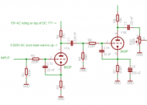
I've reduced the circuit to absurdity so all that remains powered up is the input section (named V1A in schematic below). Other section (V1B) has its heater active because there's no way to not power it, but it has anode voltage physically disconnected so it's just sitting idle. Other tubes have their heater disconnected.
I've also remodelled the PSU to more traditional CRCRC and removed a bunch of components, where values are (from rectifier bridge towards the tube): 80 uF, 100R, 100 uF, 470R, 100 uF.
220R + 22 nF from a 33 KHz LP filter which should prevent oscillations. Both components are soldered directly to socket pins.
With INPUT shorted to ground (using a clip-lead) I get 255 DC + what appears to be 15V AC at the top side of 27K anode resistor and 165V + 0.020V AC at the anode (B+ is a bit on the high side because there are no other tubes in circuit; it's normal when everything is connected).
Any attempt to view the frequency of that supposed AC results in lowest-rating PSU resistor(s) burning up. Yep, I tried it again this morning
This entire situation doesn't make any sense, I've never seen anything like this before (then again I haven't dealt with guitar amplifiers before either). I've never had an amplifier behave in such manner
I think I'm going to cut the heater of the input tube as well and see what the meter says about PSU output loaded by nothing than bleeder resistor. I have to wait for ages for PSU capacitors to discharge to safe level now that I removed majority of the loads from circuit.
I think I'm also going to try to increase the value of grid stoppers or capacitance to cathode.
After that, I'm out of ideas
Attachments
Last edited:
OK, finally some progress: while I'm awaiting propper cable (shielded) for the socket. I've planted 22 nF grid-cathode capacitors EVERYWHERE, including grid of the output tubes, to serve in conjunction with grid stoppers. The difference is that now I can virtually silence this damn thing using guitar's own volume potentiometer at rather loud amplifier volume setting, indicating that majority of leftover noise (be it hum or whatever) is coming via guitar cable, cable socket and the bit of cable connecting the socket to the board.
I think I'm going to switch the floating paraphase PI for cathodyne PI (fewer components and lower value components = fewer high impedance nodes for noise pickup) as there is obviously no need for *that* much gain (amplifier's 100K volume potentiometer is turned down to less than 6K (= 96K : 5.9K so signal is attenuated roughly -24 dB).
I think I'm going to switch the floating paraphase PI for cathodyne PI (fewer components and lower value components = fewer high impedance nodes for noise pickup) as there is obviously no need for *that* much gain (amplifier's 100K volume potentiometer is turned down to less than 6K (= 96K : 5.9K so signal is attenuated roughly -24 dB).
this damn thing
Frustrating, isn't it? First guitar amp always is. My guitar amps are pretty free of noise, it helps a lot to shield the guitar.
- Status
- This old topic is closed. If you want to reopen this topic, contact a moderator using the "Report Post" button.
- Home
- Live Sound
- Instruments and Amps
- Guitar amplifier PSU hum woes