I know that 12b4A preamps are old news, but they are fun none the less and a good challenge with excellent sound quality. So here is my latest that I present for critical review and possibilities to improve. All comments are welcome as I have not put this in a chassis yet with the expectation of some ideas to improve it and/or correct my errors.
The goal, Low Noise, Low Distortion, Minimal Gain, High Bandwidth. No intentional Feedback. Also minimize the tube tendancy to be microphonic and vibration sensitive.
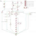
The Method To the madness. 250Vct, tube rectification, CLC filter with Hash element. 280Volts into a Salas HV Shunt Regulator holding 220V. Then to a Wavebourn Gyrator for a Load. From previous experimentation, I chose LED bias that is bypassed.
12b4 Operating Point. 130V Anode, 16V bias, with 15mA idle current. I chose this point based on a series of measurements previous to this build to identify a reasonable lower current, low thd operating point.
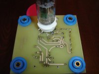
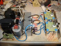
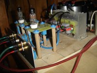
I also wanted to eliminate some of the issues of the 12b4 by mechanically isolating the tube from the chassis.
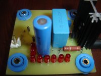
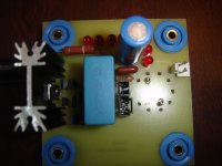
Attached is the schematic of the gyrator loaded circuit, followed by pictures of the etched and loaded pcb.
The goal, Low Noise, Low Distortion, Minimal Gain, High Bandwidth. No intentional Feedback. Also minimize the tube tendancy to be microphonic and vibration sensitive.
The Method To the madness. 250Vct, tube rectification, CLC filter with Hash element. 280Volts into a Salas HV Shunt Regulator holding 220V. Then to a Wavebourn Gyrator for a Load. From previous experimentation, I chose LED bias that is bypassed.
12b4 Operating Point. 130V Anode, 16V bias, with 15mA idle current. I chose this point based on a series of measurements previous to this build to identify a reasonable lower current, low thd operating point.
I also wanted to eliminate some of the issues of the 12b4 by mechanically isolating the tube from the chassis.
Attached is the schematic of the gyrator loaded circuit, followed by pictures of the etched and loaded pcb.
Attachments
cont.
I forgot to mention that the filament is regulated DC that is lifted to 20V.
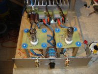
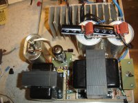
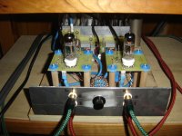
In the following photos the stereo prototype test bed is assembled and commisioned.
As it turns out the heat sink wasn't vented well enough so it was raised off of the board by 1 cm to promote better airflow. In addition the current was dropped from 63mA to 45mA (which is still a little strong) in the shunt reg to reduce heat.
I forgot to mention that the filament is regulated DC that is lifted to 20V.
In the following photos the stereo prototype test bed is assembled and commisioned.
As it turns out the heat sink wasn't vented well enough so it was raised off of the board by 1 cm to promote better airflow. In addition the current was dropped from 63mA to 45mA (which is still a little strong) in the shunt reg to reduce heat.
Attachments
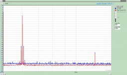
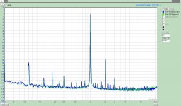
The Measurements:
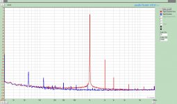
It hit the limit of my current test set-up with respect to noise. In the following 1Vrms = 0dBs.
The first FFT is the baseline measurement with and without a 1kHz signal.
The second on shows a 1 kHz comparison versus a more conventional OD3-CCS loaded 12b4A
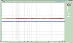
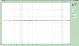
The third plot is a freq sweep of the Gyrator vs. the CCS.
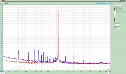
Finally the fourth plot shows IMD of the Gyrator vs. CCS.
The Gyrator loaded unit measured 0.0117% THD with a s/n ratio of 78db.
It hit the limit of my current test set-up with respect to noise. In the following 1Vrms = 0dBs.
The first FFT is the baseline measurement with and without a 1kHz signal.
The second on shows a 1 kHz comparison versus a more conventional OD3-CCS loaded 12b4A
The third plot is a freq sweep of the Gyrator vs. the CCS.
Finally the fourth plot shows IMD of the Gyrator vs. CCS.
The Gyrator loaded unit measured 0.0117% THD with a s/n ratio of 78db.
Attachments
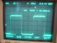
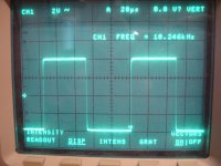
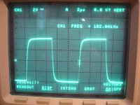
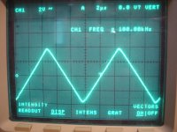
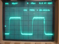
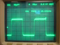
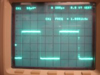
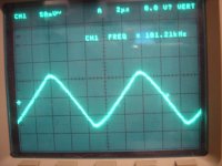
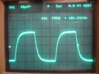
The following photos are of the square wave response at 1kHz, 10kHz, 20kHz, and 100kHz.
I tried to hit a perfect triangle at 250kHz but not quite there.
I tried to hit a perfect triangle at 250kHz but not quite there.
Attachments
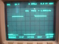
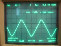
As a comparison these are of the CCS loaded 12b4 that was replaced.
Obviously the original ccs unit was having a hard time at the higher frequencies
Obviously the original ccs unit was having a hard time at the higher frequencies
Attachments
In summary, the gyrator loaded 12b4 presented here is starting to approach my goals. Mechanically, I need to soften the mechaical isolators and possibly add some weight to the pcboard. It is a HUGE difference than from running it rigidly coupled to the chassis.
Electrically, it is certainly a huge step in the right direction. Without getting too far in explanation and descriptions, it is very musical, very quite, and very detailed.
I need to get back to listen some more ;-)
The question now is what else can I do to improve it?
Electrically, it is certainly a huge step in the right direction. Without getting too far in explanation and descriptions, it is very musical, very quite, and very detailed.
I need to get back to listen some more ;-)
The question now is what else can I do to improve it?
I purchased the gomments from Grainger. Look under Isolation Bushings. I will see if I can find them and post a link
In the final Chasis, the pcbboards will be suspended from the top plate, but your idea of the copper can be made to work.
Thanks.
Try This. It was from McMaster Carr and not grainger
http://www.mcmaster.com/#vibration-isolators/=aenvzf
In the final Chasis, the pcbboards will be suspended from the top plate, but your idea of the copper can be made to work.
Thanks.
Try This. It was from McMaster Carr and not grainger
http://www.mcmaster.com/#vibration-isolators/=aenvzf
Last edited:
In the final Chasis, the pcbboards will be suspended from the top plate, but your idea of the copper can be made to work.
That's my idea for a #26 line stage: copper sheet (1.5 mm thick I've in my workshop) with two UX4 socket suspended from the top with some elastic bushing or even spring. Still to be elaborated
")
What type of CCS did you use in your previous version?
My question as well. A CCS and gyrator should have nearly identical HF response, with the CCS maintaining gain to a lower frequency.
I used both a single mosfet and a 10M45S in the previous preamp. The 10M45S is the ccs used in the data for comparison as it is what is in my old 12b4.
In the new preamp, the boards are designed to be "standard". I have a pcb designed using a cascode mosfet ccs which will be tried and documented some point in the future.
In the new preamp, the boards are designed to be "standard". I have a pcb designed using a cascode mosfet ccs which will be tried and documented some point in the future.
I agree the 10M45S is just ok.
To answer your second question I attached two measurements taken from the test stand using an earlier verion of the gyrator. In these plots the operating point are identical with the difference being bypassed LED or Not:
210V input to gyrator 130V to the anode 13.6mA bias current with 16.4Vbias. The bypass was 660uF FC type.
In general I saw no change in distortion at 1kHz, A slight increase in gain (0.1dB), but a flatter frequency response.
THD w/o bypass 0.0123% and with bypass 0.0124%
Attachments
Last edited:
Hey DT,
I am going to refrain from responding on how it sounds for a little while. I'll say that all is good and it is a step in the right direction. I only have about 10 hours listening on it.
This prototype version is still using cheap 4.7uF polypro coupling caps. I need to pop in my good ones before I'll comment more. I hope you understand.
Scott
Very nice results and great documentation.
Yes, do check out the cascode CCS variant. The cascode configuration reduces the capacitance of the MOSFETs by a large amount. In my testing the 10M45S measured similar to a IRF820. The IRF820 cascode reduced the capacitance by a factor of 55, from 4.4pf to .08pf. I didn't measure a 10M45S cascode as I only had one 10M45S at the time.
In AudioTester, if you go to Analyze/Dialog and look in the "Measuring Text Result" area you can turn on some on screen measurements that will copy with your screen shots. This will add some nice detail to your images. Also, at the top of the analyzer display where it says remark you can enter descriptive text about the test setup.
- Status
- This old topic is closed. If you want to reopen this topic, contact a moderator using the "Report Post" button.
- Home
- Amplifiers
- Tubes / Valves
- Gyrator Loaded 12b4A: The Latest Version.