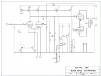
Attached is the first schematic for another bratty push-pull amp using a pair of 6LR8 triode-pentode vertical deflection tubes per side. The 6LU8 would work just as well - same tube, different pinout. The schematic as shown has all the bell and whistles, and I'll decide how many of them I want to keep as I go on.
Options - balance control, regulated screen/not, also whether I want to use the electronic cathode bias circuit or a mess of LEDs instead (maybe Stu, just maybe). I bought the Electronic Goldmine jumbo pack of 2000 pieces of 3mm green LED (1 cent each!) so I'll be prepared if I decide to do that. I figure 5 parallel strands of 7 LEDs in series would make the nut and treat the LEDs pretty conservatively.
Options - balance control, regulated screen/not, also whether I want to use the electronic cathode bias circuit or a mess of LEDs instead (maybe Stu, just maybe). I bought the Electronic Goldmine jumbo pack of 2000 pieces of 3mm green LED (1 cent each!) so I'll be prepared if I decide to do that. I figure 5 parallel strands of 7 LEDs in series would make the nut and treat the LEDs pretty conservatively.
Attachments
 ).
).Is the current mirror above the triodes actually producing matched outputs? I see a path thru two junctions to two 475 OHm resistors in parallel for the right side triode plate.
I did once see a schematic for a duplex current mirror by J.L. Hood which had high Z loading on both sides and complementary outputs (like a CT inductor load). I can't remember how it worked though, and in fact I couldn't figure out how it worked when I saw it. But I'm sure it must have. Sure would like to see it again.
I did once see a schematic for a duplex current mirror by J.L. Hood which had high Z loading on both sides and complementary outputs (like a CT inductor load). I can't remember how it worked though, and in fact I couldn't figure out how it worked when I saw it. But I'm sure it must have. Sure would like to see it again.
I'm not sure why the cathode CCS with the mirror?
If you simply hold both plates at constant current
and put a resistor under the cathodes, the same....
Seriously, would a pair of Mu followers on top, and
a single cathode resistor have been any different?
Or even two entirely separate cathode resistors?
The current U-Turn at the cathodes is meaningless
if both paths held equal elsewhere.
You specifically asked for argument...
Last edited:
First - the whole purpose of the amp is to do it with just the 6LR8s and some semi helpers, so no extra tubes, no mu followers, etc. There's no room on the top of my chosen case for any extras, anyway. The topology of differential amp/splitter into pentode outputs will remain the same.
Smoking Amp - Google "Wilson Current Mirror".
I neglected to put the XFMR impedance in. I'll be using a pair of transformers stolen from old Wurlitzer organ amps. Each transformer originally worked off a pair of 7868s. They measure out as ~6200 ohms : 8 ohms, with respectable primary inductance. A bonus is that they fit inside the case.
Current U-turn at the differential cathodes? That's a cascoded JFET current source. I'll probably be replacing it with a single Supertex TO-92 depletion mode mosfet - high impedance, fewer parts. Set thetotal current in the two tubes with a rod of iron, make it equal....
I don't doubt that the Wilson current mirror works to copy the current. Its that the input impedance to it, for the right triode, is very low, freezing the voltage swing there. You could put a resistor in series to it I guess, but then what is the point of the mirror? (the CCS tail, as Ken mentioned, is already making for complementary currents)
I assume the intention is to get the active equivalent of a center tapped plate load inductor. What you may want is the J.L. Hood complementary mirror, to get complementary Mu gains on each side. Or there is a simpler setup with two CCS plate loads (1/2 the bottom CCS) with cross-coupled resistors to control the current reference levels as complements.
I assume the intention is to get the active equivalent of a center tapped plate load inductor. What you may want is the J.L. Hood complementary mirror, to get complementary Mu gains on each side. Or there is a simpler setup with two CCS plate loads (1/2 the bottom CCS) with cross-coupled resistors to control the current reference levels as complements.
First - the whole purpose of the amp is to do it with just the 6LR8s and some semi helpers, so no extra tubes, no mu followers, etc. There's no room on the top of my chosen case for any extras, anyway. The topology of differential amp/splitter into pentode outputs will remain the same.
Smoking Amp - Google "Wilson Current Mirror".
I neglected to put the XFMR impedance in. I'll be using a pair of transformers stolen from old Wurlitzer organ amps. Each transformer originally worked off a pair of 7868s. They measure out as ~6200 ohms : 8 ohms, with respectable primary inductance. A bonus is that they fit inside the case.
Current U-turn at the differential cathodes? That's a cascoded JFET current source. I'll probably be replacing it with a single Supertex TO-92 depletion mode mosfet - high impedance, fewer parts. Set thetotal current in the two tubes with a rod of iron, make it equal....
How did you determine the load impedance of the tubes would be well matched for your transformers?
Ahh, this new "current mirror(s)" version has the look and feel of the J.L. Hood mirror I recall seeing in Wireless World some time ago. I assume Q4 sets the total current, and Q3 sets the base voltage level for the Q1 and Q2 mirrors. Still mystifies me that the Q1,Q2 collector voltages can convey any control over the collector currents. Maybe the Early effects of Q1,Q2 unbalance the teetery base voltages?
Hmm.. Or is this just two equal CCS loads for the plates? ( I think the J.L. Hood setup was claimed as complementary currents, sorta like a CT inductor)
If so, then what if you make R3 and R5 in the latest as the same resistor. Then the two currents have to be summing to the reference current.
Is there a name for this mirror(s) circuit if it is actually producing complementary currents?
If this complementary mirror scheme works well, then Sayonara to CT plate load inductors from now on. At least for low power stages anyway.
----------- Sorry about the streaming edits. Think I got it right finally.
Last edited:
Kinda looks like the input of a bipolar IC, but the current mirror is only one sided, one side of the mirror is a constant DC voltage, the other swings between the collectors, errr collector and plate.
The second design sets the VBE of both output current sources, the 1k desensitizes the design to VBE/IC variation, so now you loose the mirror to just current sources and improved linearity and differential output. You could make one of the 1k's a pot to balance the stage. In IC's we would use a NPN mirror on the bottom to run the diff pair off of the same bias resister. Again you can use a mismatch in the emitter resisters to set the current ratio. A pot would make it adjustable.. Quite a hybrid circuit.
The MPS trans are only good to 300V with a beta of 20-40
How did you determine the load impedance of the tubes would be well matched for your transformers?
The load impedance applied to pentodes can vary over quite a wide range especially when feedback is applied. When experimenting with a tube that you haven't used before and no data is given (like using a sweep tube for audio) it is best to either experiment, or look for a tube of similar size where the plate curves at least look similar and start there. In this case the pentode section of a 6LU8 / 6LR8 is somewhat like a 6V6 with the cathode from a 6W6. The 6V6 data sheet shows an 8K to 10K load. The fatter cathode in the 6LU8 will work just fine with a 6.2K load. It should crank out 20 WPC or more.
Something like this for a complementary mirror load. Q1 and Q2 are P channel Mosfets. R1 and R2 around a Meg-Ohm. Although this is the more obvious way of making one. J.L. Hood's version looked more clever as I recall. To the point that I couldn't figure it out. I don't think it had any control resistors down to the drains.
Maybe it had extra P-chan source followers driving R1 and R2, so as to not load down the outputs. Just guessing.
Hmmm, or how about a floating NPN cascode set below Q1 and Q2. Current into their bases from Q1,Q2 drains would determine the output currents (xBeta) and the control voltages for R1,R2 could come from the base voltages. Wild speculation.
Attachments
Last edited:
Well, I don't know how J.L.H. did it, but I've figured out how to do it without any loading on the outputs now. Call it the Cas-complement mirror. Q1 thru Q4 are P channel Mosfets. Q3 and Q4 can be low voltage types. R1 and R2 around a 100K Ohm say still. Q3 and Q4 act as floating cascodes in the downward direction, and as source followers in the upward direction. A class act.
edit: Hmmm,, Errr... except one could also call Q3 and Q4 low voltage zeners. Guess they aren't doing much useful. Nevermind.
edit: Hmmm,, Errr... except one could also call Q3 and Q4 low voltage zeners. Guess they aren't doing much useful. Nevermind.
Attachments
Last edited:
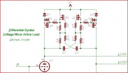
How about the differerntial gyrator?
http://www.diyaudio.com/forums/tubes-valves/118725-another-kind-hybrid-18.html#post1478402
I have an improved version but the basic concept is the same.
Cheers,
Michael
http://www.diyaudio.com/forums/tubes-valves/118725-another-kind-hybrid-18.html#post1478402
I have an improved version but the basic concept is the same.
Cheers,
Michael
Attachments
Last edited:
Yeah, Michaels got the differential load in fit form. I still would like to find that J.L.H. version someday. (was an old W. W. article for a SS amp)
Spud Re-Hashed!
Nice scaleability of current thru-out! Laser trimmed? Was it Zilog that did a CPU chip once that had an IC socket on the back? Two compactron sockets topside could be tight.
Brings to mind an interesting chassis design. Put all the parts in a long rectangular case, similar to an IC DIP shape, with a bunch of shiny "lead wires" sticking out along the bottom edges for springy support, and the compactrons plugged into the topside. Toroid OT inside out of sight. Power supply from an umbilical. A small notch in one end of the chassis for orientation. Epoxy black finish. A new meaning to "integrated amp".
Last edited:
Looking at Michael's Differential Gyrator schematic(s) using caps in the cross coupling controls gives me an idea on how to eliminate the residual V sense resistor loading (for AC) on the tube outputs. Since the current drawn by those V sense resistors is predictable, one could use Hawksford's cascode compensation technique to remove the same currents from the Mosfet outputs.
Need some resistance in series with the D1,D2 Zeners, and a small cap (like pF) from R9 and R12 top ends (improved version posted) (or could just use another set of sense resistors) to the same side Mosfet sources. Idea is to subtract out from the Mosfet current (at it's source) the same tiny AC current as drawn by the sense resistors, making them transparent effectively.
Need some resistance in series with the D1,D2 Zeners, and a small cap (like pF) from R9 and R12 top ends (improved version posted) (or could just use another set of sense resistors) to the same side Mosfet sources. Idea is to subtract out from the Mosfet current (at it's source) the same tiny AC current as drawn by the sense resistors, making them transparent effectively.
Last edited:
- Status
- This old topic is closed. If you want to reopen this topic, contact a moderator using the "Report Post" button.
- Home
- Amplifiers
- Tubes / Valves
- Happy New Year - A New Amp to Argue About...