I have searched extensively for information on Volume Control with no success. Any help I can get is appreciated.
I’m in the design stage of a 5-6+ watt SE 6BQ5. I haven’t decided on what to use for the gain stage. I’m Leaning towards a 6DJ8/6N1P-EV. (Suggestions?)
The problem I’m trying to solve is to have at least 200 degrees rotation on the pot and not over drive the grids. With out some attenuation I have found it’s easy to over drive the gain and/or output stage grids. (12-14V P-P as an output stage as a reference). This is true even with medium Mu valves.
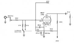
Attached is the attenuation design I used in the past. Although it works I have concerns about problems I may have induced that will become apparent on more powerful amps. The switch allows me to select between two attenuation values. This is helpful because I use this amp with a lot of different sources.
To the point, have I exposed myself to harmful grid leak? The Rg values are far below those listed in the R-C chart. The other concern is the Rg value when the pot is in the full on position.
Have I induced distortion?
Is there a better way to do this? (Different Tube, Design in less gain, etc?)
Do you have a better design? (Simple, not stepped)
T
I’m in the design stage of a 5-6+ watt SE 6BQ5. I haven’t decided on what to use for the gain stage. I’m Leaning towards a 6DJ8/6N1P-EV. (Suggestions?)
The problem I’m trying to solve is to have at least 200 degrees rotation on the pot and not over drive the grids. With out some attenuation I have found it’s easy to over drive the gain and/or output stage grids. (12-14V P-P as an output stage as a reference). This is true even with medium Mu valves.
Attached is the attenuation design I used in the past. Although it works I have concerns about problems I may have induced that will become apparent on more powerful amps. The switch allows me to select between two attenuation values. This is helpful because I use this amp with a lot of different sources.
To the point, have I exposed myself to harmful grid leak? The Rg values are far below those listed in the R-C chart. The other concern is the Rg value when the pot is in the full on position.
Have I induced distortion?
Is there a better way to do this? (Different Tube, Design in less gain, etc?)
Do you have a better design? (Simple, not stepped)
T
Attachments
None of my power amps have or need input attenuation, so I am puzzled as to what you are using to drive your power amps that is causing such an issue. Can you elaborate?
I use a line stage that controls the system volume level and that is all I have found I need.
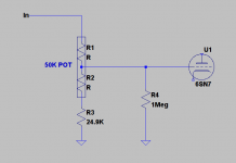
I would probably use a simpler circuit than shown if I needed some attenuation. Variable attenuation can be accomplished with as few as a single low value pot, and two resistors. See my example.. (Note that grid stopper is omitted here. I feel their inclusion is a good idea for EMI. ) Note that this attenuator provides a continuous range of 0 to -10dB of attenuation. Changing the ratio by tinkering with the pot value and R3 can provide a greater range of attenuation as required. Input Z of network shown is ~75K..
Building amplifiers with just the right amount of gain is also a good idea..
I use a line stage that controls the system volume level and that is all I have found I need.
I would probably use a simpler circuit than shown if I needed some attenuation. Variable attenuation can be accomplished with as few as a single low value pot, and two resistors. See my example.. (Note that grid stopper is omitted here. I feel their inclusion is a good idea for EMI. ) Note that this attenuator provides a continuous range of 0 to -10dB of attenuation. Changing the ratio by tinkering with the pot value and R3 can provide a greater range of attenuation as required. Input Z of network shown is ~75K..
Building amplifiers with just the right amount of gain is also a good idea..
Attachments
Last edited:
None of my power amps have or need input attenuation, so I am puzzled as to what you are using to drive your power amps that is causing such an issue. Can you elaborate?
I use a line stage that controls the system volume level and that is all I have found I need.
I would probably use a simpler circuit than shown if I needed some attenuation. Variable attenuation can be accomplished with as few as a single low value pot, and two resistors. See my example.. (Note that grid stopper is omitted here. I feel their inclusion is a good idea for EMI. ) Note that this attenuator provides a continuous range of 0 to -10dB of attenuation. Changing the ratio by tinkering with the pot value and R3 can provide a greater range of attenuation as required. Input Z of network shown is ~75K..
Building amplifiers with just the right amount of gain is also a good idea..
Would your circuit be considered a modified bridged T attenuator?
Last edited:
Thanks Kevin,
Sources are Reciever, CD Payer, PC Sound Card, Mp3 Player, cable box, etc.
I'm trying to avoid the need for a line stage, except for phono.
Thanks for the diagram. I'll throw a spread sheet together and run some numbers.
Can you expand on "Building amplifiers with just the right amount of gain" or at least point me in a direction? The options I see are tube selection and/or going way off the R-C charts and designing a circuit with less gain.
Would your circuit be considered a modified bridged T attenuator?
It's just a classic voltage divider with a restricted adjustment range. R4 is there simply to provide a grid circuit dc path in the event that the pot wiper goes open - it has almost no effect on the normal operation of the circuit as it is more than 25X greater in value than the highest possible source impedance to the following triode input stage.
To be a bridged T the impedance at both ports would have to be constant at all values of attenuation, and while that criteria is more or less met on the input side, the output side has a wide range of impedances depending on the pot position and driving source impedance. I assumed this network would be driven by a source with a relatively low and constant source impedance - the attenuation values cited are based on a driving source impedance of 0 ohms.
Last edited:
Thanks Kevin,
Sources are Reciever, CD Payer, PC Sound Card, Mp3 Player, cable box, etc.
I'm trying to avoid the need for a line stage, except for phono.
Thanks for the diagram. I'll throw a spread sheet together and run some numbers.
Can you expand on "Building amplifiers with just the right amount of gain" or at least point me in a direction? The options I see are tube selection and/or going way off the R-C charts and designing a circuit with less gain.
I wouldn't go too far off the charts as you will invariably end up with plate loads that result in excessive distortion.
I would select tubes that provide the least gain required to do the job. Look at 6SN7/6FQ7/6J5/12B4 and other moderate to very low mu types. Local feedback can be used to reduce gain further. Could be as simple as unbypassed cathode in the voltage amplifier with caveats of course. (Higher rp, somewhat more noise and distortion - in most cases an acceptable compromise if taken into consideration during design.)
The simplest thing to do is simply build the amplifier with a conventional volume control and use that to control the overall level while setting the sources to provide their maximum unclipped output.
I recommend Morgan Jones "Valve Amplifiers, 3rd Edition" if you don't have it already. Should be a great help, and it's a fun read as well.
Last edited:
Thanks Kevin,
I was first looking at using a 6FQ7 but wanted to build something I could try Russian tubes in. I guess you can't have everything. Back to the 6FQ7.
Regarding the 6FQ7/6CG7. I'm going with about 6mA per your advice from the other day. I still don't understand why when using most R-C chart values the mA is so low the curves are still very curved and messy.
You recommended "Valve Amplifiers" the other day. Just got it today. At a glance it should take me a lot farther than "Beginner's Guide to Tube Audio Design: Rozenblit".
Gotcha, thanks for the reply.
It's just a classic voltage divider with a restricted adjustment range. R4 is there simply to provide a grid circuit dc path in the event that the pot wiper goes open - it has almost no effect on the normal operation of the circuit as it is more than 25X greater in value than the highest possible source impedance to the following triode input stage.
To be a bridged T the impedance at both ports would have to be constant at all values of attenuation, and while that criteria is more or less met on the input side, the output side has a wide range of impedances depending on the pot position and driving source impedance. I assumed this network would be driven by a source with a relatively low and constant source impedance - the attenuation values cited are based on a driving source impedance of 0 ohms.
Regarding the 6FQ7/6CG7. I'm going with about 6mA per your advice from the other day. I still don't understand why when using most R-C chart values the mA is so low the curves are still very curved and messy.
I've often wondered about that myself, but I usually run them at pretty high currents - the penalty of course is that a higher supply voltage is required, and in most applications that's not really a significant issue.
A plate load resistance of >3 times rp will net you good linearity, CCS loading is also an option, probably a better choice if you have limited B+.
You recommended "Valve Amplifiers" the other day. Just got it today. At a glance it should take me a lot farther than "Beginner's Guide to Tube Audio Design: Rozenblit".
MJs books are well written, informative, and entertaining in a way few authors match. I find the lack of ego refreshingly appropriate. It will take you far indeed.
It is not usually a good idea to make the wiper-track contact part of the volume potential divider, as this is a poor quality resistor. Better to use the track as the divider, then the wiper-track contact feeds into a higher impedance such as a valve grid with a suitable grid leak to ground. The question to ask is "what happens when the wiper-track contact resistance changes?"
- Status
- This old topic is closed. If you want to reopen this topic, contact a moderator using the "Report Post" button.
- Home
- Amplifiers
- Tubes / Valves
- Volume Control Help!