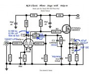
Kevin mentioned a mediocre phono section. The attached tweaked RCA setup would (IMO) deal nicely with that issue. Little TO92 case LR8 3 terminal regulators (1/channel) would take care of making the B+ rail, whatever voltage it happens to be, the requisite 250 V.
If an exact schematic can't be rounded up, look here. That thread has a PP 6BM8 schematic you can use with some confidence.
I strongly advise disposing of the tone controls and any filters, as part of the refurbishment. Most of the time, that stuff wrecks the sound and FEW recordings benefit from them.
Attachments
Thanks Eli - mind a few more questions?
How will this particular schematic assist my repair guy (who is highly competent) if it is not for the exact unit?
Knowing that topographies are much of the "magic", is there anything of particular note I should pass on to my guy about this schematic?
Lastly, I need to replace the four 6BM8 tubes. I've seen a variety on eBay, including supposedly new ones from the Ukraine and other areas. Any advice? All matched Mullards (most expensive it seems)? Russina types perfectly fine? Middle of the road suggestions?
I am still learning - I know the tubes matter, perhaps they matter most but I do not really know. Thoughts are most welcome...
I appreciate your help - thanks for the quick reply on the schematic.
Cheers.
I'm not a fan of Flea Pay. It's too much like Dodge City, KS, before Wyatt Earp arrived.  Buy your tubes from a reputable vendor, of which there are several. FWIW, I prefer Jim McShane, but he's definitely not the only game in town.
You need pairs of 6BM8s, whose power sections are well matched, for both gm and cathode current. The GNFB loop takes care of differences in the small signal triodes. Russian 6BM8s are pretty good and (IMO) there's little reason at this time to buy COSTLY Mullards.
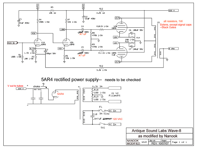
As for the schematic, that topology of voltage amplifier DC coupled to a "concertina" phase splitter and on to PP "finals" is very well proven. Fisher, Scott, and Dyna used it and it's probably OEM in your unit. The ASL AV-8 has drawn its share of favorable remarks. So, the parts values are worthy of some respect.
Buy your tubes from a reputable vendor, of which there are several. FWIW, I prefer Jim McShane, but he's definitely not the only game in town.You need pairs of 6BM8s, whose power sections are well matched, for both gm and cathode current. The GNFB loop takes care of differences in the small signal triodes. Russian 6BM8s are pretty good and (IMO) there's little reason at this time to buy COSTLY Mullards.
As for the schematic, that topology of voltage amplifier DC coupled to a "concertina" phase splitter and on to PP "finals" is very well proven. Fisher, Scott, and Dyna used it and it's probably OEM in your unit. The ASL AV-8 has drawn its share of favorable remarks. So, the parts values are worthy of some respect.
Thanks Eli - mind a few more questions?
How will this particular schematic assist my repair guy (who is highly competent) if it is not for the exact unit?
Knowing that topographies are much of the "magic", is there anything of particular note I should pass on to my guy about this schematic?
Lastly, I need to replace the four 6BM8 tubes. I've seen a variety on eBay, including supposedly new ones from the Ukraine and other areas. Any advice? All matched Mullards (most expensive it seems)? Russina types perfectly fine? Middle of the road suggestions?
I am still learning - I know the tubes matter, perhaps they matter most but I do not really know. Thoughts are most welcome...
I appreciate your help - thanks for the quick reply on the schematic.
Cheers.
The associated SAF-24 amp schematic for your/our model is on my 6bm8 amp project thread..
I am planning, by December to build this amp FROM SCRATCH! I had the original schematic and owners manual from the amp that I had lost in a move.
Cewl - being lazy (and searching and not finding it) can you post the link? Why are you building this design?
Here is the original schematic link from my thread. //2.bp.blogspot.com/-Yth_TIVnZVs/TWwjVYmiMHI/AAAAAAAAAA0/0vC7f4fFOyM/s1600/saf24amp.jpg
Like you, I had the original amp. when I got it I was happy with how it worked until the old crufty caps started to go. I lost it when I moved. I still have the original manual and schematic so... why not rebuild it and improve the design where needed. it was certainly loud enough for my 12'x12' living room. I still have the original Garrard 210 that came with the set at a tag sale in 1985. Replaed the ancient shure conical magnetic cartridge about 20 years ago with a R25XT elliptical cartridge and a new idler wheel.(replaced last year). it is connected to my Optimus SSM1250 4 channel mixer via the magnetic photo input. Its solid state and I missed the old 6bm8 tube sound.
They put the tone controls in the NFB loop. The "concertina" phase splitter is cap. coupled to the voltage amplifier, which may or may not cause phase shift trouble. FWIW, I have a distinct preference for the AV-8 and its (IMO) less troubling topology. If a few more Volts are needed in the B+ rail to make DC coupling work, SS rectify it.
If you are going use AC heating, as shown, for the phono section, the ONLY choice for the tubes is the Sovtek 12AX7LPS. The 'LPS is a genuine 7025 equivalent built with hum bucking, spiral wound, heaters.
The "concertina" phase splitter is cap. coupled to the voltage amplifier, which may or may not cause phase shift trouble. FWIW, I have a distinct preference for the AV-8 and its (IMO) less troubling topology. If a few more Volts are needed in the B+ rail to make DC coupling work, SS rectify it.If you are going use AC heating, as shown, for the phono section, the ONLY choice for the tubes is the Sovtek 12AX7LPS. The 'LPS is a genuine 7025 equivalent built with hum bucking, spiral wound, heaters.
They put the tone controls in the NFB loop.
If you are going use AC heating, as shown, for the phono section, the ONLY choice for the tubes is the Sovtek 12AX7LPS. The 'LPS is a genuine 7025 equivalent built with hum bucking, spiral wound, heaters.
for the 12ax7 filaments I was considering using twisted pair and home running it to the 6.3vac taps or using the buss topology. Thus canceling much of the noise. (originally the amp didn't have a hummmmm problem due to this in the phono stage. it was the dodgy caps. Recordings to a cassette unit that I had showed no hum in the inputs from the tape-out jack. Turntable at that time had a dried out idler wheel that made RUMBLE but not hum.
HOWEVER. uisng SS diodes other than for the half wave rectified grid bias isn't my plans. I am going to be using a 5u4gb tube (already bought) for the full wave rectifer since the 6ca4 was much harder to get at a reasonable price.
IF I did got with SS rectification... I need to add a delay circuit or a B+ enable switch to protect the tubes from cathode rot. I am considering either one as then the 5u4gb that has a directly heated filiment can get hot and ready before it feeds the other tubes that have indirectly heated filaments.
Unlike the original. I want to use a 6 position make before break double pole switch to allow me to add more inputs. one 1/8" stereo on the front, one 1/8" Stereo tape out on the front. along with a 1/4" 16ohm headphone jack that is connected via the 16ohm taps of the opts. I also want to add speaker disable switch to allow the headphones to be used with or without the speakers active;.
The remainder of the knob positions would be for phono, tape, tuner, aux1 (front) and aux2(front) and aux3(front).
I will keep the Ceramic and magnetic cartridge inputs since my two turntables are both! (the Ceramic is a Realistic Opimus turntable that I found on the street. the original magnatic cartridge I had no idea what stylii it used. I bought an Astatic ceramic cartridge and made the turntable into my back up that works on my Voice Of Music 6V6 mono portable box amp from 1955. Great for outdoor music.
On the safety side is the updated UL electrical standards of a earthed chassis and a properly fused mains plug. You are not to tie the chassis to the FUSED side of the line! Its against UL and NEC electrical code!
- Status
- This old topic is closed. If you want to reopen this topic, contact a moderator using the "Report Post" button.
- Home
- Amplifiers
- Tubes / Valves
- Realistic Stereo 24